


229.—Holding a Round Shaft,
Page 38
Page 39
If you've noticed an error in this article please click here to report it so we can fix it.
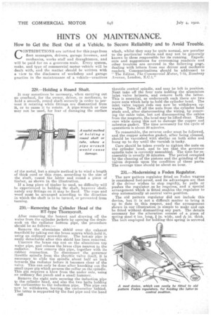
It may sometimes be necessary, when carrying out an overhaul, for the owner, driver, or mechanic, to hold a smooth, round shaft securely in order to pervent it rotating while fittings arc dismantled from it, or to cause it to rotate. A pipe-wrench or vice may not be used, for fear of damaging the surface of the metal, but a simple method is to wind a length of thick cord or thin rope, according to the size of the shaft, round the latter and round a piece of timber, as shown in the illustration.
If a long piece of timber be used, no difficulty will be experienced in holding the shaft, however obstinately any fittings on it may be fixed. The rope and wood must be arranged according to the direction in which the shaft is to he turned, or prevented from turning.
230.—Removing the Cylinder Head of the BT-type Thornycroft.
After removing the bonnet and drawing off the water from the cylinder jackets by opening the draincock on the radiator bottom pipe, the procedure should be as follows :— Remove the aluminium shitld over the exhaust manifold by taking out the brass screws which .hold it, using an ordinary screwdriver. The hot-air pipe is easily detachable after this shield has been removed. Unscrew the brass cap nut on the aluminium top water pipe, and release the brass clips nearest tothe radiator. Now remove this pipe, together with its rubber connection. To disconnect the governor throttle spindle from the throttle valve itself, it is necessary to slide the spindle about half an inch towards the radiator before it becomes clear of the valve. This can only be done after knocking out the small taper pin which secures the collar on the spindle. This pin requires a blow from the under side, using an ordinary flat punch and a small hammer.
Remove the eight nuts securing the induction pipe to the cylinder head, and also the two bolts holding the carburetter to the induction pipe. This pipe can now be withdrawn, leaving the carburetter behind. The latter is supported 44 the fuel pipe and the hand 012 throttle control spindle, and may be left in position. Next take off the four nuts holding the aluminium inlet valve helmets, and remove both the latter. This is essential, as underneath each there arc twomore nuts which help to hold the cylinder head. The inlet valve tappet rods can now be withdrawn upwards. Take off all the nuts from the cylinder head studs and, after disbonnecting the wiring, by removing the cable tube, but not disconnecting the cables from the magneto, the head may be lifted clear. Take care while doing this not to damage the copper and asbestos gasket. The time necessary for the cycle of operations is about 20 minutes.
To reassemble, the reverse order must be followed, and the copper asbestos gasket, after being cleaned, should be varnished with. shellac on both sides and hung up to dry until the varnish is tacky.
Care should be taken evenly to tighten the nuts on the cylinder head, and to see that the governor spindle tube is correctly assembled. The time for reassembly is usually 30 minutes. The period occupied by the cleaning of the pistons and the grinding of the valves depends upon the condition of these parts. The average time should be about an hour. '
231.—Modernizing a Foden Regulator.
The new pattern regulator fitted on Foden wagons is considered fool-proof, and its advantages are that if the driver wishes to stop rapidly, he pulls or pushes the regulator, as he requires, and a special arrangement which is fitted enables the regulator to stop automatically at central valve position.
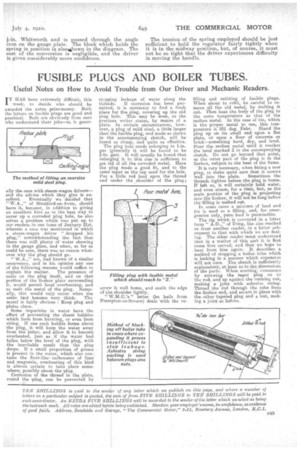
The old pattern regulator did not include this device, but it is. not a difficult matter to bring it up to date in this respect, and the arrangement shown in our illustration is simple to make and can be fitted without dismantling any part. The details necessary for the alteration consist of a piece of spring steel 6 ins, long, in. wide, and ak in, thick. The bolt employed for holding this spring is screwed
i-in. Whitworth and is passed through the angle iron on the gauge plate. The block which holds the spring in position is alsokihown in the diagram. The cost of the conversion is negligible, and the driver is given considerably more confidence. The tension of the spring employed should be just sufficient to hold the regulator fairly tightly when it is in the midway position, but, of course, it must not be so tight that the driver experiences difficulty in moving the handle.