


Ventilation System for Double-deckers
Page 58
If you've noticed an error in this article please click here to report it so we can fix it.
o ventilate.lx)th decks of a double1 decker without materially absorbing valuable space, is the aim of a scheme disclosed by R. Fone, 84, Liverpool Road,
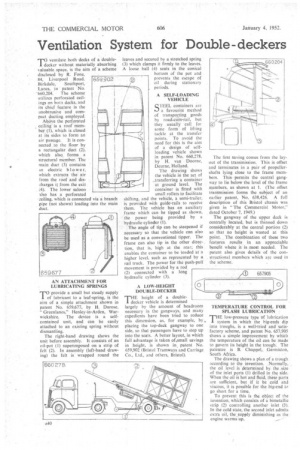
Birkdale, Southport, Lanes, in patent No. 660,204. The scheme utilizes perforated ceilings on both decks, and its chief feature is the unobtrusive and compact ducting employed.
Ahave the perforated ceiling is a roof member. (1), which is closed at its sides to form an air passage. It is connected to the floor by a rectangular duct (2), which also forms a structural member. The main duct (3) contains an electric blower, which extracts the air from the roof and discharges i from the exit (4). The lower saloon also has a perforated ceiling, which is connected via a branch pipe (not shown) leading into the main duct. 65g,902
AN ATTACHMENT FOR LUBRICATING SPRINGS
To provide a small but steady supply of lubricant to a leaf-spring, is the aim of a simple attachment shown in patent No. 659,677, by H. Durose, " Greenlanes," Henley-in-Arden, Warwickshire. The device is a selfcontained unit, and can be easily attached to an existing spring without dismantling.
The right-hand drawing shows the unit before assembly. It consists of an oil-pot (I) superimposed on a strip of felt (2). In assembly (left-hand drawing) the felt is ' wrapped round the leaves and secured by a stretched spring (3) which clamps it firmly to the leaves. A loose ball (4) seats in the conical bottom of the pot and (.)1 prevents the escape of oil during stationary periods.
A SELF-LOADING VEHICLE QTEEL containers are ).-.) a favourite method of transpovting goods by road-cum-rail, but they usually call for some form of lifting tackle at the transfer points. To avoid the need for this is the aim of a design of selfloading vehicle shown in patent No. 660,278, by H. van Doorne, Deurne, Holland.
The drawing shows the vehicle in the act of _transferring a container at ground level. The container is fitted with small rollers to facilitate shifting. and the vehicle, a semi-trailer, is provided with guide-rails to receive them. The vehicle has an auxiliary frame which can be tipped as shown, the power being provided by a hydraulic cylinder (1).
The angle of tip can be steepened if necessary so that the vehicle can also be used as a conventional tipper. The frame can also tip in the other direction, that is, high at the rear; this enables the container to be loaded at a higher level, such as represented by a rail truck. The power for the push-pull
movement is provided by a rod (2) connected with a long hydraulic cylinder (3).
A LOW-HEIGHT DOUBLE-DECKER
THE height of a doubledecker vehicle is determined largely by the amount of headroom necessary in the gangways, and many expedients have been tried to reduce this dimension, as, for example, by placing the top-deck gangway to one side, so that passengers have to step up into the seats. A better layout, in which full advantage is taken of 'small savings in height, is shown in, patent No. 659,902 (Bristol Tramways and Carriage Co., Ltd., and others, Bristol). The first saving comes from the layout of the transmission. This is offset and terminates in a pair of propellershafts lying close to the frame members. This -permits the central gangway to lie below the level of the frame members, as shown at 1. (The offset transmission forms the subject of an earlier patent, No. 638.426. A full description of this Bristol chassis was given in "The Commercial Motor," dated October 7, 1949.)
The gangway of the upper deck is centrally located, but is thinned down considerably at the central portion (2) so that no height is wasted at this point. The combination of these two features results in an appreciable benefit where it is most needed. The patent also gives details of the con. structional members which are used in the scheme.
TEMPERATURE CONTROL FOR SPLASH LUBRICATION ,
THE low-pressure type of lubrication system in which the big-ends dip into troughs, is a well-tried. and 'satisfactory scheme, and patent No. 657,905 shows a simple improvement by which the temperature of the oil can be made to govern its height in the trough: The patentee is B. Chappel, Germiston, South. Africa.
The drawing shows a plan of a trough according to the invention. .Normally, the oil level is determinedbythe .size of the inlet ports (1) 'drilled in the side. When the oil is hot and fluid, these ports are sufficient, but if it be 'cold and viscous, it is possible for the big-end to go short for a time.
To prevent this is the object of the invention, which consists of a bimetallic strip (2) controlling another inlet (3). In the cold state, the second inlet admits extra oil, the supply diminishing as the engine warms up.