


A Compact Multi-cylindered Oil Engine
Page 42
If you've noticed an error in this article please click here to report it so we can fix it.
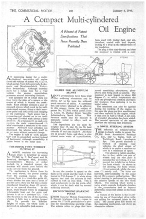
AN interesting design for a multicylindered two-stroke • oil engine forms the subject of patent No. 572.354, which comes from Schweizerische Lokornotiv und Maschinenfabrik, Winterthur Switzerland Although intended more for a railcar than for a road vehicle, the engine, nevertheless, possesses several interesting features.
The cylinders (1) of which there are four form the sides of a square, at the centre of which is located the crankshaft Each cylinder contains a pair of °noosed pistons which work in the wellunderstood manner. firing at their innermost point and exhausting and charging ai the outermost. Each piston has a connecting-rod pivoted on to an oscillating arm (2) which rocks about a fixed pivot (3). An extension (4) on each arm receives the main connecting-rod (5) which surrounds a crankpin in the usual manner Although four cylinders are illustrated, the scheme lends itself to six or more without material change.
The engine is said to work equally well with its crankshaft vertical instead of horizontal, although accessibility is rather better in the latter case.
DIRASHING CO1RN WITHOUT CUTTING IT ANOVEL machine for harvesting grain crops is described in patent No 572.040 by F. McConnel and D. Bomford, Bevington Hall, Evesham, Worcestershire. Drawn. or rather pushed, by a standard tractor, the machine will thrash corn before the stalks are cut from the ground.
Thf mechanism is driven from its own road wheels, the power coming from the pushing tractor. In the extreme front is a comb-like guide (1), which divides the corn into a series of parallel lows; these are fed into a multichambered thrashing drum (2) revolv ing in an upward direction. In the drum. multi-bladed rotors in staggered relationship beat out the grain and denosit it on to a conveyor (3). This lifts /he prain to the top of the machine, whence it falls into a sacking hopper (41. To provide for different beights of crops, the whole outfit is mounted on adjustable jack-screws. SOLDER FOR ALUMINIUM ALLOYS
MANY preparations have been tried 1V-Lfor soldering aluminium and its alloys, out so far none has achieved much measure of utility. A combined flux and solder, claimed to be effective in this respect, forms the subject of patent No. 572,010, which comes from L. Louis, 36, Dunbar Street, Yeoville,
Johannesburg, South Africa. This inventor states that his mixture is especially suited to alloys such as duralumin.
The ingredients are (in parts by weight): lead 13, zinc 32, tin 50, lead chloride 9, zinc chloride 30, ammonium chloride 37 and zinc oxide 9. All these are in powder form, and there is also present some water of crystallization.
In use, the powder is spread on the faces to be joined and the work is then heated to 230 degrees C. A white dross appears and then the mixture is well rubbed in with an iron stick. This is said satisfactorily to tin the work, after which it can be dealt with by normal soldering methods.
RECONDITIONING SPARKING PLUGS CROM General Motors Corporation, Detroit, Michigan, US.A., comes, in patent No. 572,434, particulars of a process for reconditioning sparking plugs. The scheme refers to plugs that have
pound containing phosphorus, phosphoric acid being cited as suitable. The insulator is next heated to about 800 degrees C., at which temperature the lead and phosphorus combine and leave the insulator, thus restoring it to its initial value.
The treatment can also be applied during the working of the engine; in this case the plugs,are first sand-blasted and then replaced in the engine, which is then run on fuel to which .3 per cent. of trimethyl phosphate has been added. The normal operation of the engine provides the ensuing heat treatment.
A NOVEL STEERING SYSTEM
THE influence of military-vehicle design is clearly visible in patent No. 572,316, from Automotive Products Co., Ltd., and G. Gates, both of
Tachbrook Road, Leamington Spa. This patent discloses a method of steering road vehicles, the chief object of which is to enable a machine to, turn in a minimum of space.
The scheme is rather unorthodox in that, whilst one pair of wheels (say the rear _ pair) is mounted for swivelling, it is not steered, but is left free to follow the front wheels. As shown in the drawing, the front wheels (1) are .powered, whilst the rear ones (2) merely trail. The latter are however, inter-connected by the .usual tie-rod (3) to ensure unified action. The actual steering is performed by varying the relative speeds of the two front wheels. The steering wheel works a valve which controls hydraulic clutches in the atransrnission and so imparts differential rotational speeds to the front wheels.
A feature of the design is that it permits the use of front-wheel drive without calling for universal joints in the axles. The patent gives full details of the operating mechanism, and shows an alternative scheme.