


THE LATH' INGLE-DECKER BUS CHASSIS
Page 30
Page 31
Page 32
If you've noticed an error in this article please click here to report it so we can fix it.
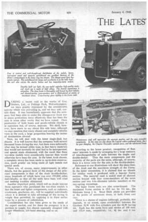
DU RING a recent visit to the works of Guy Motors, Ltd., at Fallings Park, Wolverhampton, we were greatly impressed by the considerable activity which was prevailing in, and we may add, outside them. It was immediately apparent that the company had been able to make the change-over from war to peace production more effectively than has been the case in some other works that we have visited. Flow production of both buses and goods-vehicle chassis is in operation but, of course, separate. We shall, however, have more to say about this side later, although we may mention that many chassis and complete vehicles were in the yard, a large proportion bearing the names of destinations abroad.
Now, we will deal with the latest single-deck bus chassis. It is well known that the company built several thousand buses duringithe war, but these were enforcedly what may be termed utility type, in that heavy materials that would not normally be used had to be incorporated, and special steels eliminated, with the result that these war-time models were considerably heavier than would otherwise have been the case. In the latest Arab chassis. a complete return has been made to up-to-date construction, much greater use being made of light metals and special steels.
There are, of course, many improvements in other details, but the general basis of the design of the principal components is that of the Arab double-decker, many hundreds of which have run over 250,000 miles individually, so that all the units have been well tried and teething troubles eliminated.
Another important point, which will no doubt interest those operators who purchased the war-time models is that the latest and lighter components, such as radiators, crankcases, gearboxes, etc., will be supplied individually . where it is desired to take advantage of the saving in weight thus permitted, by applying it to these earlier types by a process of substitution.
Consideration has also been given to the needs of the export market, and for these the company is in a position to supply bus chassis especially designed with longer wheelbase, left-hand steering, and so on.
pe Reverting to the home product, recognition of fleet users' interests is made by arranging for a large measure of interchangeabality of units between the singleand double-decker. Thus the main components and the majority of the parts are the same, although, of course, there is a lower ratio for the axle in the double-decker.
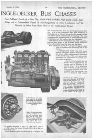
Reference to our illustrations will show the clean lines of the Arab and the enormous strength of the frame. In the latter connection, it is claimed that no chassis for similar work is produced with a heavier frame section. The material used is nickel steel of channel section braced with four cross-members of the same section and two 4-in.-diameter tubular members at the rear-spring mountings,
The taper frame ends are also cross-braced. The maximum frame section is 10+1. ins. by 21-7r ins., the
thickness being in. Stout flitch plates are provided at the points of maximum stress, at both front and rear.
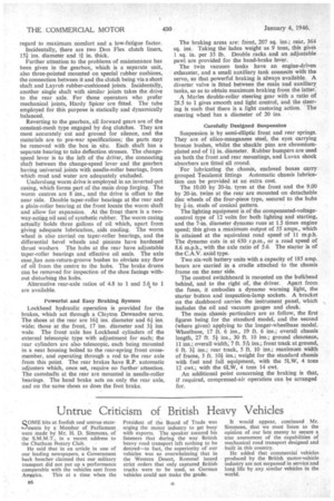
There is a choice of engines (although, probably, this depends, to an extent, upon availability) between the Gardner 5LW with five cylinders and the 6LW having six. Each has the same bore and stroke of 108 mm. and 152.4 mm., respectively. i.e., 4+ ins, and 6 ins that employed on the Arab has proved particularly effective. It is of the three-point type, with Silentblocs at the front, and, at the rear, a semi-circular casing in which are rubber inserts, resilient and oil-resisting. The front mountings also include springs to absorb low-frequency oscillations, and the anchor pins are lubricated.
The clutch is of the single-plate type with a cast-iron bearing plate bolted to the flywheel, ample ventilation being afforded between this plate and the latter.
Fuel injection is by a C.A.V. pump, drawing its supply from a 28-gallon tank on the off side of the chassis.
A spring-loaded clutch stop and exceptionally light pedal pressure ease the task of the driver, whilst maintenance is facilitated by the clutch being of the open type so that adjustment or replacement is simple, also the cooling is effective.
An unusual practice LI that the driver's seat is supplied with the chassis and is included in the chassis price. It is adjustable both vertically and horizontally. The driving controls have been modified from the previous type and are designed with special regard to maximum comfort and a low-fatigue factor. Incidentally, there are two Don Flex clutch liners, 15.i ins, diameter and it in. thick.
Further attention to the problems of maintenance has been given in the gearbox, which is a separate unit, also three-pointed mounted on special rubber cushions, the connection between it and the clutch being via a short shaft and Layrub rubber-cushioned joints. Incidentally, another single shaft with similar joints takes the drive to the rear axle. For those operators who prefer mechanical joints, Hardy Spicer are fitted. The tube employed for this purpose is statically and dynamically balanced.
Reverting to the gearbox, all forward gears are of the constant-mesh type engaged by dog clutches. They are most accurately cut and ground for silence, and the materials are to pre-war specifications; the parts may be removed with the box in situ. Each shaft has a separate bearing to take deflection stresses. The changespeed lever is to the left of the driver, the connecting shaft between the change-speed lever and the gearbox having universal joints with needle-roller bearings, from which mud and water are adequately excluded.
Underslung worm drive is employed in an inverted-pot casing, which forms part of the main drop forging. The worm centres are 8 ins., and the drive is offset to the near side. Double taper-roller bearings at the rear and a plain-roller bearing at the front locate the worm shaft and allow for expansion. At the front there is a twoway-acting oil seal of synthetic rubber. The worm casing actually holds three gallons of oil which, apart from giving adequate lubrication, aids cooling. The worm wheel is also carried on taper-roller bearings, and the differential bevel wheels and pinions have hardened thrust washers The hubs at the rear have adjustable taper-roller bearings and effective oil seals. The axle case has non-return-groove bushes to obviate any flow of oil from the centre to the hubs. The brake drums can be removed for inspection of the shoe facings without disturbing the hubs.
Alternative rear-axle ratios of 4.8 to I and 5.6 to 1 are available.
Powerful and Easy Braking System Lockheed hydraulic operation is provided for the brakes, which act through a Clayton Dewandre servo. The shoes at the rear are 16/ ins, diameter and 61 ins. wide; those at the front, 17 ins, diameter and 31 ins. wide. The front axle has Lockheed cylinders of the external telescopic type with adjustment for each; the rear cylinders are also telescopic, each being mounted in a neat housing bolted to the rear-spring front crossmember, and operating through a rod to the rear axle from this point. The rear brakes have R.P. automatic adjusters which, once set, require no further attention. The camshafts at the rear are mounted in needle-roller bearings. The hand brake acts on only the rear axle, and on the same shoes as does the foot brake. The braking areas are: front, 207 sq. ins.; rear, 364 sq. ins. Taking the laden weight as 9 tons, this gives 1 sq. in. per 35 lb. Double racks and an adjustable pawl are provided for the hand-brake lever.
The twin vacuum tanks have an engine-driven exhauster, and a small auxiliary tank connects with the servo, so that powerful braking is always available. A diverter valve is fitted between the main and auxiliary tanks, so as to obtain maximum braking from the latter.
A Marles double-roller steering gear with a ratio of 28.5 to 1 gives smooth and light control, and the steering is such that there is a light castoring action. The steering wheel has a diameter of 20 ins.
Carefully Designed Suspension Suspension is by semi-elliptic front and rear springs. They are of silico-manganese steel, the eyes carrying bronze bushes, whilst the shackle pins are chromiumplated and of 11 in. diameter. Rubber bumpers are used on both the front and rear mountings, and Luvax shock absorbers are fitted all round.
For lubricating the chassis, enclosed boxes carry grouped Tecalemit fittings Automatic chassis lubrication can be provided at an extra cost.
The 10.00 by 20-in. tyres at the front and the 9.00 by 20-in, twins at the rear are mounted on detachable disc wheels of the four-piece type, secured to the hubs by i-in. studs of conical pattern.
The lighting equipment is of the compensated-voltagecontrol type of 12 volts for both lighting and starting, and the 7-in, diameter dynamo runs at 1.5 times engine speed; this gives a maximum output of 55 amps., which is attained at the equivalent road speed of 11 m.p.h. The dynamo cuts in at 650 r.p.m., or a road speed of 8.6 m.p.h., with the axle ratio of 5.6. The starter is of the C.A.V. axial type.
Two six-volt battery units with a capacity of 185 amp. hours are carried in a cradle attached to the chassis frame on the near side.
The control switchboard is mounted on the bulkhead behind, and to the right of, the driver. Apart from the fuses, it embodies a dynamo warning light, the starter button and inspection-lamp sockets. A bracket on the dashboard carries the instrument panel, which includes the oil and vacuum gauges and clock.
The main chassis. particulars are as follow, the first figures being for the standard model, and the second (where given) applying to the longer-wheelbase model. Wheelbase, 17 ft. 6 ins., 19 ft. 6 ins.; overall chassis length, 27 ft. 51ins., 30 ft. 10 ins.; ground clearance, 11 ins.; overall width; 7 ft. 5-Pe ins.; front track at ground, 6 ft. 3i ins.; rear track, 5 ft. 10 ins.; maximum width of frame, 3 ft. 10.k ins.; weight for the standard chassis with fuel and full equipment, with the 5LW, 4 tons 12 cwt.; with the 6LW, 4 tons 14 cwt.
An additional point concerning the braking is that, if required, compressed-air operation can be arranged for.