


HINTS ON OVERHAULING.
Page 12
Page 13
Page 14
Page 15
If you've noticed an error in this article please click here to report it so we can fix it.
(4)The Dennis 3-4 ton Chassis. An Accessible Design—The Value of a Well Illustrated and Arranged Spare Parts List.
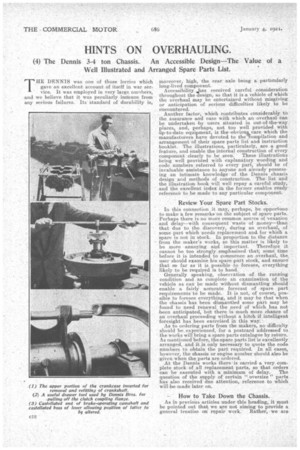
THE DENNIS was one of those lorries which gave an excellent account of itself in war srvice. It was employed in very large numbers, and we believe that it was peculiarly immune from any serious failures. Its standard of durability is,
moreover, high, the rear axle being a particularly long-lived component. Accessibility as received careful consideration throughout the design, so that it is a vehicle of which the overhaul may be entertained without raisgiving or anticipation of serious difficulties likely to be encountered.
Another factor, which contributes considerably to the assurance and ease with which an overhaul can be undertaken by users situated in out-of-the-way places, and, perhaps, not too well provided with up-to-date equipment, is the obviouLeare which the manufacturers have devoted to theEompilation and arrangement of their spare parts list, and instruction booklet. The illustrations, particularly, are a good feature, and enable the internal construction of every component clearly to be seen. These •illustrations being well provided with explanatory wording and code numbers referred to every part, should be of invaluable assistance to anyone not already possessing an intimate knowledge of the Dennis chassis design and methods of construction. The list and the illustration book will well repay a careful study, and the excellent index in the former enables ready reference to be made to any particular component.
Review Your Spare Part Stocks.
In this connection it may, perhaps, be opportune to make a few remarks on the subject of spare parts. Perhaps there is no more common source of vexation and delay--with consequent waste of money—than that due to the discovery, during an overhaul, of some part which needs replacement and. for which a spare is not in stock. In proportion to the distance from the maker's works, so this matter is likely to be more annoying and important. Therefore it cannot be too strongly emphasized that; some time before it is intended to pornmence an overhaul, the, user should examine his spare part stock, and ensure that so far as it is possible to foresee, everything likely to be required is to hand: Generally speaking, observation of the running condition and as complete an examination of the vehicle as can be made without dismantling should enable a fairly accurate forecast of spare part requirements to be made. It is not, of course, possible to foresee everything, and it may be that When the chassis has been dismantled some part may be found to need renewal the need of which has not 'been anticipated, but there is much more chance of an overhaul proceeding without a hitch if intelligent foresight has been exercised in this way.
As to ordering parts from the makers, no difficulty should be experienced, for a postcard addressed to the works will bring a spare parts catalogue by return. As mentioned before, the spare parts list is excellently . arranged, and it is only necessary to quote the code numbers to obtain the part required. In all cases, however, the chassis or engine number should also be given when the parts are ordered.
At the Dennis works there is carried a very complete stock of all replacement parts, so that orders can be executed with a minimum of delay. The question of the ;supply of certain "oversize " parts has also received due attention, reference to which will be made later on.
How to Take Down the Chassis.
As in previous articles under this heading, it must be pointed out that we are not aiming to provide a general treatise on repair work. Rather, we are
seeking to assist in various ways the man who lacks intimate acquaintance and expert knowledge of the vehicle in question. In addition' we present such information as the makers have been good enough to let us have on the question of special points peouliar to the vehicle .-to which special attention should be paid and of the manner in which they preferably should be handled.
In. commencing to dismantle the 3-4 ton Dennis chassis, the guard in front of the radiator, together with the lamp brackets on either side, must first be removed; then cast loose the front end of the radiator stay rod, .uncouple the hose connections, remove the caps from the trunnion brackets which ' support the radiator,and the latter can be lifted off. In. order to avoid the possibility of subsequent damage, it is next advisable perhaps to remove the fan, by slacking off the set screw at the back of the bracket which grips the sliding stem on which the spindle housing is carried,
Removing Dath and Engine.
The next job is to remove the dash, after disconnecting all the controls and the piping attached to it. It is not essential to remove the steering box and column in order to get the engine out of the frame, so that may be allowed to remain in position, if desired. The clutch operating lever links should now be disconnected, at the knuckle end, by the removal of the link pins, and the nuts removed from the universal joints on the clutch coupling shaft, so that the socket sleeves can be moved towards the centre of the shaft, and the latter removed, together with its pins and blocks. The engine can then be lifted out of the chassis with the clutch still in position.
We are assuming that itis desired completely to dismantle the chassis for overhaul and inspection, but as occasions may possibly arise in which it is desirable to rcmove the clutch without disturbance of the engine, it may be as well to give here a few hints as regards the dismantlement and care of this component.
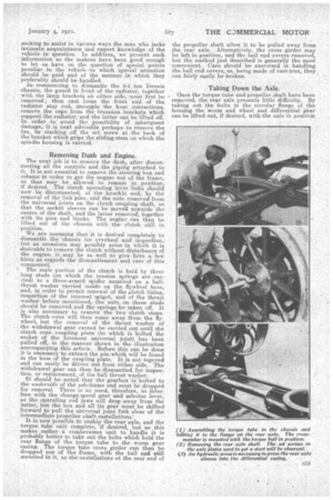
\ The male portion of the clutch is held by three long studs (on which the tension springs are ,carried) to a three-armed spider mounted on a ballthrust washer carried inside on the flywheel boss, and, in order to permit renewal of the ,clutch
inspection of the internal spigot, and of the thrust washer before mentioned, the nuts, on these studs should be removed and the springs be taken off. It is also necessary to remove the two clutch stops. The clutch cone will then come away from the flywheel, but the removal of the thrust washer of the withdrawal gear cannot be carried out until the clutch cone coupling plate (to which is bolted the socket of the foremost universal joint) has been pulled off, in the manner shown in the illustration accompanying this article, Before this can be done it is necessary to extract the pin which will be found in the boss of the coupling plate. It is not tapered and can easily be driven out from either side. The withdrawal gear can then be dismantled for inspection, or replacement, of the ball thrust washer.
it should be_noted that the gearbox is, bolted to the underside of the sub-frame 'and must be dropped for removal. There is no needs therefore, to interfere with the change-speed gear and selector lever, as the operating rod jaws will drop away from the latter, but the box and all its gear must be shifted forward to pull the universal joint fork clear of the intermediate propeller shaft castellations: It is now possible to unship the rear axle, and the torque tube unit complete, if desired, but as this makes rather a cumbersome unit to handle it is probably better to take out the bolts which hold the rear flange of the torque tube to the worm gear ca-sing. The torque tube cross girder can then be dropped out of the frame, with the ball end still ,nounted in it, as the eastellations at the rear end of
the propeller shaft allow it to be pulled away from the rear axle. Alternatively, the cross girder may be left in position, and the ball end covers removed, but the method just described is generally the most convenient. Care should be exercised in handling the ball end covers, as, being made of cast-iron, they , can fairly easily be broken.
Taking Down the Axle.
Once the torque tube and propeller shaft have been emoved, the rear axle presents little difficulty. By inking out the bolts in the circular flange of the housing the worm and wheel and differential gear can be lifted out, if desired, with the axle in position
in the chassis. It is first necessary to withdraw the axle shafts---a, matter of unbolting the driving plates on either side and pulling them out., The driving plates are 'provided with. two tapped holes in which set screws can be inserted to facilitate the initial stage of this operation. After the brake rod ends have been uncoupled from the operating levers, the axle can be run back on its wheels, on the removal of the spring shackle bolts, with the• springs still in position.
As regards these latter, while it is not advisable, unless an expert spring smith is available, to endeavour to set them up if their camber has been found to be unequal or reduced, it should be noted
that the manufacturers carry a stock of replacement leaves of. all required lengths, to enable repairs to be executed when necessary. 13ushes and shackle bolts for repIacenient purposes are of course -also obtainable.
Attention should be giv,en to the condition of the four bolts which hold each spring on to the axle It is possible sometimes that under repeated tightening, of the nuts a little stretch may have taken place, which the condition of that--ttortion of the thread jusSAinderneath the nut wiWindicate. If stretch has occiiired, the diameter there will be slightly reduced, in which case new belts should be fitted.
The remeval of the. front axle is similarly accomplished,.. and the same .remarks apply to the treat ment, of the siisPensiOn details. The frame, thus relieved of its main aimponeets, should of course be examined 'all over, and the rivets tried for tightness. If-a loose rivet be fotind, it should be replaced by a good quality, well-fitting bolt.
Engine Peculiarities.
The dismantling of the engine should present little difficulty. The front cover can be removed with the magneto and water pump in situ, if desired. Very complete instructions as to the care of the magneto are given in the Dennis instruction book, so there is no need to go into the matter here. A point to which attention should be given on the water pump is the conaition of the fibre washer on the pump spindle, which serves the purpose of the packing
more usually fitted to such pumps. Care should A also be taken that the drain hole, on the underside of the easing, just behind this washer, is perfectly clear, otherwise water may find its way along the pump spindle to the timing gear casing. In ta.king.up the big-ends it is always advisable either to use a special set of bolts or to fit new ones when the bedding-down operations have been completed. Generally speaking, it is wise to leave the governor untouched. It is just possible, however, that the 014 springs may require renewal if the engine has been inclined to hunt" when running.
Should it be found on examination that the cylinder bores are so worn as to require regrinding, and facilities are available, they should be reground either to 1011,000 of an inch oversize, or, if badly, scored for any reason so that they will not clean up to that dimension, to 20-I,000 eversize, as the makers are in a position to supply replacement pistons to suit.
Similarly, should it be found that the crankshaft journals are in need of truing up, they should be reground either 104,000 in. undersize, or 20-1,000 in., i
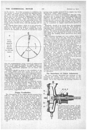
as bearings to correspond are kept n stock by the makers. In taking up the big-ends it is always advisable either to use a special set of bolts or to fit new ones when the bedding down operations have been completed. The camshaft bearings are very seldom likely to require renewal, but if for any reason it is desired. to remove either of the camshafts and their bearings, they will be found to be held in position by set screws the heads of which are on the outside of the crankcase. These must he removed before the shafts, together with their bearings, can be withdrawn. It should be noted that the exhaust camshaft is hollow and forms part of the oil conduit system. At its rear end is situated the oil release valve, and if this is taken down it is very important to take care that it is correctly reassembled. This precaution, needless to say, applies to all portions of the mechanism; as regards the reassembly of the carburetter And induction pipe particularly, great care must be taken to remake all points so as to prevent the slightest possibility of air leakage. Another point to remember is that the final adjustment of the valve tappets, after the valves have been reground, is preferably made when the engine has been run and is warm, in order to allow for expansion. As regards the timing of the engine, little difficulty should be experienced, as the flywheel rim is marked to correspond with top dead centre, inlet opening, inlet closing, exhaust opening, and' exhaust closing, in accordance with the timing diagram which we reproduce.
The Importance of Clutch Adjustment.
We have already described the methods of dismantling the' clutch, and a few remarks on the matter of its assembly and adjustment may now be useful. It is very important to arrange matters so
that when the pressure is removed from the clutch pedal there is a little " play" in the connections. It should be possible to pull the pedal up from the floorboards about in. This ensures that the link which connects the pedal to the withdrawal gear is not interfering with the proper engagement of the clutch. When the vehicle is in use this adjustment should also be examined from time to time, as, when the clutch lining wears, the link must be lengthened slightly if clntch slip is to be prevented. In adjusting the spring pressure it is important to ensure that all three springs are adjusted alike, that is to say, that an equal number of turns is given to each of the three nuts on the ends: of the spring studs. The clutch stops must also be adjusted carefully so that the pads come into operation before the clutch pedal can come into contact with the floorboards.
The gearbox is of simple design, and the shafts can be withdrawn by the removal of the end covers. It should be noted that the correct meshing of the gears is provided for by an adjustment on the selector rods. By loosening the two nuts at the jaw end, and moving them along the serrated faces, the relative positions of the sliding pinions, as controlled by the change speed lever, can be varied. Care should be taken to see that the square rods underneath the gearbox are well lubricated, and that the springloaded plungers, which engage with the .notches in these rods, are working freely and that the springs do not require replacement.
The footbrake should be carefully adjusted and all moving parts well lubricated. It should be noted that the side levers are provided with set screws, which should be so adjusted that the shoes completely clear the drum when the brake is "off." Ex:cessive slackness in the universal joints must be rectified by rebushing. It will be found that there is a packing ring, between the rear half of the torque ball housing and the cross girder which carries it, by which any slackness there may be taken up. Reference his already been made to the ease with which the rear axle can be dismantled. If the worm and differential unit is dis-assembled for any reason, great care must be taken in reassembling. Particu
lady must careful attention be paid to the mounting of the worm and wheel, to see that the parts are central and in line and that the worm takes its proper bearing on the worm wheel. It is unlikely that these two parts will require renewal, unless, by some negligence, they have been permitted to run absolutely without any lubricant whatever. Care should be taken that there is no end-play in any of the thrust bearings.
The Adjustment of the Brake.
As the side brake shoes are not provided with renewable fabric or other lining, specialattention should be given to the matter of their adjustment. It will be noticed that each shoe is provided with a small plate, against which the brake cam operates. These plates are renewable and if much wear of the shoe faces has taken place renewable, substitution of thicker
plates enables the brakes to operate without excessive cam movement.
As regards the latter, it will be noted that the end of the brake camshaft is splined. This enables the position of the operating lever, relative to the cam, to be altered so that the lever is in the most advantageous position from the point of view of leverage. It should be remembered that the side brakes should hold when the hand lever is half-way down the quadrant, and all acljustnients should be made accordingly.
Both front and rear wheels are mounted on bronze floating bushes, to which ample dimensions ensure a, long life, provided that lubrication has received proper attention. Oversize bushes can be supplied by the makers for replacement purposes in cases where lack of lubrication has caused wear on the wheel centres or swivel arms to necessitate truing up. End play in the wheels can be taken up by fitting thicker thrust wa,shersf or by putting thin steel washers behind the existing ones.
In the event of ndue wear or damage to the thread of the ends of the axle sleeves, it is best to return the axle casing complete to the makers, as the sleeves are pressed under heavy hydraulic pressure and it is not an easy matter to remove them without proper appliances.