


Connecting Rods From Sheet Metal
Page 34
If you've noticed an error in this article please click here to report it so we can fix it.
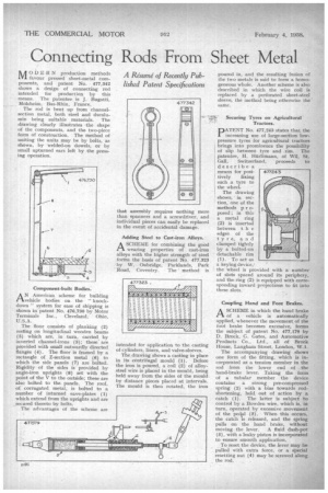
A40DERN production methods L Y1 favour pressed sheet-metal components, and patent No. 477,342 shows a design of connecting rod intended for production by this
• means. The patentee is J. Bugatti, MoIsheim, Bas-Rhin, France.
The rod is bent up from channelsection metal, both steel and duralumM being suitable materials. The drawing clearly illustrates the shape of the components, and the two-piece form of construction. • The method of uniting the units may he by bolts, as shown, by welded-on dowels, or by small upturned ears left by the pressing operation,
AN American scheme for building vehicle bodies on the• " knockdown" system for ease of shipping is shown in patent No. 476,730 by Motor Terminals Inc., Cleveland, Ohio, U. S. A .
The floor consists of planking (2) resting on longitudinal wooden beams (5) which are, in turn, carried. by inverted channel-irons (3); these are provided with small outwardly directed flanges (4). The floor is framed by a rectangle of Z-section metal (6) to which the side panels (7) are bolted. Rigidity of the sides is provided by angle-iron uprights (8) set with the point of the V to the outside; these are also bolted to the panels. The roof, of corrugated metal, is bolted to a number of inturned eave-plates (1) which extend from the uprights and are secured thereto by bolts.
The advantages of the scheme are Adding Steel to Cast-iron Alloys.
ASCHEME for combining the good wearing properties of cast-iron alloys with the higher strength of steel forms the basis of patent No. 477,323 by W. Oubridge, Parklands, Park
• Road, Coventry. The' method is that assembly requires nothing more than spanners and a screwdriver, and individual pieces can easily be replaced in the event of accidental damage.
intended for application to the casting of cylinders, liners, and valve-sleeves.
The drawing shows a casting in place in its centrifugal mould (1). Before the iron is poured, a coil (2) of alloysteel wire is placed in the mould, being held away from the sides of the mould by distance pieces placed at intervals. The mould is then rotated, the iron poured in, and the resulting 'fusion of the two metals is said to form a homogeneous whole. Another scheme is also described in which the wire coil is replaced by a perforated sheet-steel sleeve, the method being otherwise the • same.
Securing Tyres on Agricultural' Tractors.
A
*crop. pATENT No. 477,243 states that the increasing use of large-section lowpressure tyres for agricultural tractors brings into prominence the possibility of slip between tyre and rim. The patentee, H. Hinlimann, of Will, St. Gall, Switzerland, proceeds to describe a means for posi
tively fixing such a tyre to the wheel.
The drawing shows, in section, one of the methods p r oposed ; in this a metal ring (2) is inserted between t h e edges of the tyre, a n clamped tightly by a bolted-on detachable rim (1). To act as a keying device,: the wheel is provided with a number of slots spaced around its periphery, and the ring (2) is equipped with corresponding inward projections to fit into these slots.
Coupling Hand and Foot Brakes.
ASCHEME in which the hand brake of a vehicle is automatically applied, whenever the movement of the foot brake becomes excessive, forms the subject of patent No. 477,179 by D. Brock, G. Gates, and Automotive Products Co., Ltd., all of Brock House, Longhorn Street, London, V. 1.
The accompanying drawing shows one form of the fitting, which is incorporated as a tension member in the rod from the lower end of the hand-brake lever. Taking the form of a tubular member the device contains a strong pre-compressed spring (2) with a bias towards rodshortening, held out of action by a catch (1). The latter is subject to control by a Bowden wire, which is, in turn, operated by excessive movement of the pedial (3). When this occurs, the catch is released, and the spring pulls on the hand brake, without moving the lever. A fluid dash-pot (5), with a leaky piston is incorporated to ensure smooth application.
To reset the device, the lever may be pulled with extra force, or a special resetting nut (4) may be screwed along the rod.