


Pumping Test of 120 h.p. Commer-Simonis Fire Engine for Canada.
Page 8
Page 9
If you've noticed an error in this article please click here to report it so we can fix it.
in our issue dated 20th November we gave particulars of the application of. an electrical engines.i.trter to a Com.mer-Simonis fireengine.
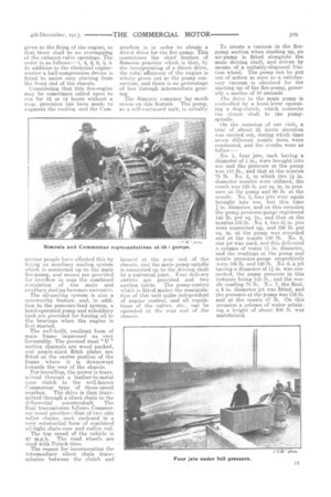
We are now in a. position to place before our readers not only the constructional features of this mammoth fire-fighting equipment, which has been under our observation for some time past, but also to give interesting particulars of a pumping test carried out last week at Walthantstow by Messrs. H. Simonis and Co.
This Conn-ilex-Shift:ids machine, which is for export tu Canada. Wa8 exhibited at Olympia in jLily last.
The. outfit consists of a Mather and Platt natent multi-stage highlift turbine pump mounted on a, specially constructed Commercar chassis. The capacity of the pump is 1000 gallons when the engine is developing 120 h.p. This same pump, however, has delivered up to 1103 gallons of water per minute. At the end of this article we give the respective pump and nozzle pressures for different sizes of jets which were used during the test.
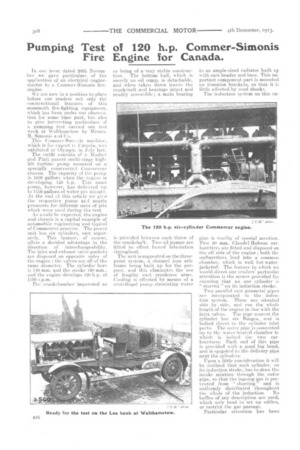
As would be expected, the engine and chassis is a capital example of automobile engineering and typical of Commercar practice. The power unit has six cylinders, cast separately. • This feature, of course, offers a decided advantage in the direction of interchangeability. The inlet and exhaust valve pockets are disposed on opposite sides of the engine ; the valves are all of the same diameter. The cylinder bore is 140 mm. and the stroke 190 mm., and the engine develops 120 h.p. at 1100 r.p.m.
The crankehamber impresge.d us as being of a very stable construc tion. The bottom half, which is merely an oil sump, is detachable, and when taken down leaves the crankshaft and hearings intact and readily accessible; a main bearing
is provided between each throw of the crankshaft.. Two oil pumps are fitted to effect forced lubrication throughout.
The unit is supported on the threepoint system, a channel iron subframe being built up for the purpose, and this eliminates the use of lengthy east crankcase arms. Cooling is effected by means of a centrifugal pump circulating water to an ample-sized radiator built up with cast header and base. This important component part is mounted on trunnion brackets, so that it little affected by road shocks.
The induction system on this en gine is worthy of special mention. Two 40 mm. ClaudeI-Hobson carburetters are fitted and disposed on the off side of the engine ; both the carburetters lead into a, common chamber, which is well hot -waterjacketed. The feature to which we would direct our readers' particula.r attention is the means provided for ensuring that no one cylinder is " starved_" on its induction stroke.
Two parallel cast gunmetal pipes are incorporated in the induction system. These are situated side by side, and rim the whole length of the engine in line with the inlet valves. The pipe nearest the cylinder has six flanges, and is bolted direct to the cylinder inlet ports. The outer pipe is connected up to the water-heated chamber to which is bolted the two carburetters. Each end of this pipe is provided with a good big bend, and is spigoted to the delivery pipe next the cylinders.
Upon a little consideration it will be realized that each cylinder, on its induction stroke, has to draw the intake mixture through the outer pipe, 80 that the in going gas is prevented from " shorting" and is uniformly distributed throughout
the whole of the induction. No baffles of any description are used, which only tend to set up eddies, or restrict the gas passage.
Particular attention has been given to the firing of the engine, so that there shall be no overlapping of the exhaust-valve openings. The order is as follows :-1, 4, 2, 6, 3, 5. In addition to the electrical enginestarter a half-compression device is fitted to assist easy starting from the front end of the chassis.
Considering that this fire-engine may be sometimes called upon to run for 12 or 14 hours without a stop, provision has been made to augment the cooling, and the Corn rn ercar people have effected this by fitting an auxiliary cooling system which is connected up to the main lire-pump, and means are provided for overflow in case the combined circulation of the main and .auxiliary Coohng becomes excessive.
The oil-cooling system is also a noteworthy feature, and, in addition to the pressure-feed system, a hand-operated pump and subsidiary tank are provided for forcing oil to the bearings when the engine is first started.
The well-built, resilient form of main frame impressed us very favourably. The pressed steel "U " section channels are wood packed, and ample-sized flitch plates are fitted at the centre portion of the frame where it is downswept towards the rear of the chassis.
For travelling, the power is transmitted through a leather-to-metal cone clutch to the well-known Commercar type of three-speed gearbox. The drive is then transmitted through a silent chain to the differential countershaft. The 'final transmission follows Commercar usual practice—that of two side Toiler chains, each enclosed in a very substantial form of combined oil-tight chain-case and radius rod.
The top speed of the vehicle is 40 m.p.h. The road wheels are shod with Polack tires.
The reason for incornorating the intermediary silent chain transmission between the clutch and gearbox is in order to obtain a direct drive for the fire-pump. This constitutes the chief feature of Simonis practice which is that, by the incorporating of a direct drive, the total efficiency of the engine is wholly given out at the pump connection, and there is no percentage of loss through intermediate gearing.
The Simonis company lay much stress on this feature. The pump, as a self-contained unit, is suitably housed at the rear end of the chassis, and the main pump-spindle is connected up to the driving shaft by a universal joint. Four delivery outlets are provided and two suction inlets. The pump-control which is fitted makes the manipulation of this unit quite independent of engine control, and all regulations of the valves, etc., can be operated at the rear end of the chassis. To create a vacuum in the fire pump suction when starting up, an air-pump is fitted alongside the main driving shaft, and driven by means of a suitably-disposed friction wheel. The pump can be put out of action as soon as a satisfactory vacuum is obtained for the starting up of the fire-pump, generally a matter of 30 seconds.
The drive to the main pump is controlled by a hand-lever operating a dog-clutch, which connects the clutch shaft to the pumpspindle.
On the occasion of our visit, a trial of about 2 hours duration was carried out, during which time seven different nozzle tests were conducted, and the results were as follow :— No. 1, four jets, each having a diameter of I. in., were brought into use and the pressure at the pump was 110 lb., and that at the nozzles 78 lb. No. 2, in which two 1/ in. diameter nozzles were utilized, the result was 125 lb. per sq. in. in pressure at the pump and 96 lb. at the nozzle. No. 3, four jets were, again brought into use, but this time / in. diameter, and on this occasion the pump pressure-gauge registered 145 lb. per sq. in., and that at the nozzles 135 lb. No. 4, two 21 in. jets were connected up, and 195 lb. per sq. in. at the pump was recorded and at the nozzle 150 lb. No. 5, one jet was used, and this delivered a column of water in. diameter, and the readings at the pump and nozzle pressure-gauge respectively were 165 lb. and 120 lb. No. 6, a jet having a diameter of 1i in. was connected, the pump pressure in this instance being 145 lb., and the nozzle reading 78 lb. No. 7, the final, a 2 in. diameter jet was fitted, and the pressure at the pump was 132 lb. and at the nozzle 47 lb. On this occasion a column of water attaining a height of about 200 ft. was maintained.