


Patents Completed.
Page 20
If you've noticed an error in this article please click here to report it so we can fix it.
Complete specifications of the following patents will be sent to any address in the United Kingdom upon receipt of eightpence per copy at the Sale Branch, Patent Office, Holborn, W.C.
THE LUBRICATION OFINTERNAL COMBUSTION ENGINES,—Renault.No. 7,848 J1910, dated, under International Convention, 19th April, 1909.— According, to this invention, a pump is arranged in the crank-chamber and is driven, in the type of construction described, by means of worm gearing mounted on the distributing shaft. The pump forces oil nom the bottom of the crank-chamber through pipes to the lower part of the main bearing j thenca the oil spreads in an annular passage surrounding the hearing and reaches the driving shaft through orifices arranged radially to the shaft. Excess of oil escapes through an orifice at the upper part of the bearing, the diameter of this orifice being, preferably, larger than that of the pipe which supplies the bearing. The oil thus flows freely through the said orifices and returns through conduits to the bottom of the crank-chamber. The oil that escapes at the ends of the bearings is projected by centrifugal force through conduits formed in the crankshaft and supplies oil to the connectingrod head.
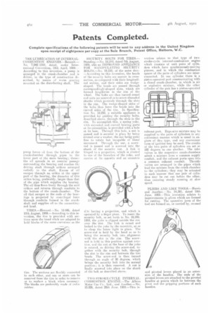
TIRES.—Iroward.—No. 18.446, dated 10th August, 1909.—According to this invention, the tire is provided with sections upon the tread whch are adapted to hold blocks of the same curvature as the tire. The sections are flexibly connected to each other, and one or more can be removed from the tire in order to remove or to replace a block when necessary. The blocks are preferably made of indiaru bber. SECURITY BOLTS FOR TIRES.Standing.—No. 18,249, dated 7th August, 1909, also an IMPROVED APPLIANCE FOR MANIPULATING SECURITY BOLTS.—No. 18,250, of the same date. —According to this invention, the heads of the security bolts are narrow in crosssection, as compared with their longitudinal section. and their sides are wedgeshaped. The heads are passed through correspondingly-shaped slots, which are formed lengthwise in the rim of the wheel. The bolts are then turned round and nuts are screwed on to screw-threaded shanks which protrude through the slots in the run. The wedge-shaped sides of the bolts thus force the beads into the curved sides of the rim. In Specification No. 18,250. a suitable appliance is provided for guiding the security bolts, described above, through the slots in the rim. To accomplish this, a spring yoke, with extended and curved bearing parts at its extremities, is provided with a hole at its base. Through this hole, a nut is passed and is secured in place by being riveted over a washer, the nut being 9uite free to rotate but incapable of lineal movement Through the nut, a screw rod is passed and is screwed into the shank of the security nut. A link is hinged to a projection, which is riveted to one of the branches of the yoke, and carries at 1t3 opposite end an eccentric (1.7c having a projection, and which is operated by a finger piece. To insert the security bolt, as set forth in No. 18,249, 1909, the yoke is clipped astride the rim over the slot. The link is raised and locked to the yoke by the eccentric, so as to clasp the latter tight in place. The screw-rod is held by the head so as to bring the security bolt into alignment with the slot in the rim. The screwrod is held in this position against rotation. and the nut at the base of the yoke is rotated, so driving the screw-rod, to. gether with the security bolt, through the slot in the rim and between the tire beads. The screw-rod is then turned through an angle of 90 degrees, which brings the security bolt into its normal position ; it is then removed, A nut is finally screwed into place on the shank of the bolt as described above.
TWO STROKE-CYCLE INTERNAL COMBUSTION ENGINE.—The Albion Motor Car Co.. Ltd., and Another—No. 15.026, dated 29th June. 1909.—This in
volition relates to that type of twostroke-cycle internal-combustion engine which consists of unit pairs of cylinders which have synchronously-moving pistons, and in which the combustion spaces of the pairs of cylinders are interconnected. In one cylinder there is a piston-operated port communicating with a closed crank-chamber, in which is air or explosive mixture, while the other cylinder of the pair has a piston-operated exhaust port. Expisasive mixture may be supplied to the pairs of cylinders in any convenient manner which is usual in engines of this type, and any convenient form of ignition may be used, The cranks of the two pairs of cylinders are set at 180 degrees to one another. The inlet valves in the respective crank-chambers admit a mixture from a common supply conduit, and the exhaust ports open intu a common exhaust conduit. Throttle valves are arranged in the pipes which lead the mixture from the crank-chamber to the cylinders ; they may be actuated in such manner that one pair of cylinders may be cut out before the other. thus ensuring steady running at slow speed.
PLIERS AND LIKE TOOLS.—Harris and Another.—No. 14,381, dated 19th June, 1909.—This inveution relates to improvements in pliers which are formed for cutting. The operative jaws of the tool are formed on, or carried by, crossed
and pivoted levers placed in an erten. sion of the handles. The ends of the pivoted levers are attached to the pivoted handles at points which lie between the pivot and the gripping portions of such handles.