


Patents Completed.
Page 20
If you've noticed an error in this article please click here to report it so we can fix it.
Complete specifications of the following patents will be sent to any address in the United Kingdom upon receipt of eightpence per copy at the Sale Branch, Patent Of lice, firs .born, WC.
EMERGENCY TIRES.—Turnbull.No. 3,543, dated 14th February, 1910.— This specification describes a supplementary rim and tire, which can be readily substituted for a damaged tire. It consists of a rim having some suitable solid resilient tire attached to it. The ordinary tire is removed from the wheel, and this rim is substituted therefore. The attachment is made by means of a number of male and female joints. One member is fixed to the outer rim, and the other is arranged to fix in the inner rim. The two members are capable of longitudinal extension with regard to one another, and, by opening them all out equally, the outer rim is securely attached to the wheel. A form of the coupling member is described which is arranged to act as a tensile member, being suitably gripped by the inner rim. Spring members may be introduced to render the wheel more resilient. Several forms of the coupling members are described.
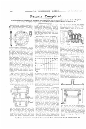
GE ARBO X.—Tacchi.—No. 8,062, dated 4th April, 1910.—This specification describes an improved form of gearbox for motor vehicles. The casing is cast in one piece and has a door formed in it for introducing the gear wheels and pinions. Hollow bossss are formed in the ends of the box to take bearings or ball races. These bosses are screwed internally, and the outer member of the ball race is fitted inside this boss. The shaft is introduced through this bearing and after the balls have been introduced the cups are adjusted. The shaft (h) is coupled to the engine shaft and has a large pinion loose upon it. The other part of this shaft is square and carries
a double pinion on it,. The drive is transmitted to the large pinion by the smaller pinions tieing clutched to it. Either of these pinions is put in mesh with the gear wheels on the other shaft for transmitting the differeut speeds. This second shaft is fitted with a forked head to engage with the coupling and the cardan or other shaft.
MA GNETO-IONITION CONTROL.— Thompson (Eiseman!' and Co.).—No. 9,4:-:, dated 19th April, 1910.—This specification relates to apparatus for automatically controlling the time of ignition according to the speed of the engine. The armature of the magneto is driven through a centrifugal governor from the engine shaft. The sliding sleeve of the governor is arranged to engage with a spiral thread formed on the shaft, so that the outward move nent of the governor balls brings about relative displacement of the armature and the driven shaft. The device is so arranged that up to a certain speed, at about a speed of 250 revolutions per minute, the ignition is retarded. but above that speed it is suddenly advanced and is arranged to advance steadily with increase of speed. This is shown graphically in the curve of the speed and angle of advance. The governor is allowed a certain amount of freedom, and, at the predetermined speed, this motion is completely taken up and any further movement is resisted by a spring which gives a proportional advance with increase of speed.
COMBINED PETROL AND STEAM ENGIN E.—Stecks.—No. 27,491, dated 26th November, 1909.—According to this specification, one of the cylinders of an internal-combustion engine is replaced by a compressor, the piston of which is coupled direct to the main crankshaft. Above this compressor cylinder is arranged a steam cylinder whose piston is fixed on the Caine piston rod as the compressor piston. Surrounding the steam cylinder, is a steam generator, which consists of an annular chamber fitted with suitable guides and baffles and directing the flow of the exhaust gases. The watcr is drawn from the fan-cooled rad'ator, possibly through a feed-water heater, and is made to circulate round the internal-combustion cylinders. These cylinders are formed with an outer casing fitting tightly. In either the cylinder wall or its outer casing, a spiral groove is formed ; water is passed in at the lower end, circulates round the cylin
der, and, becoming heated, then passes either direct to the steam generator or to circulate round the other cylinders. The exhaust gases are drawn in by the corn
pressor from the internal-combustion cylinders and are then driven out through the water in the steam generator. The steam thus formed passes by the inlet valve on to the upper side of the steam piston. It is exhausted either into the feed-water heater or direct to the radiator.
INTERNAL COMBUSTION ENGINE.—Lanehester.—No. 23,106, dated 9th October, 1909.—This invention relates to internal-combustion engines, of the kind in which a sliding-valve element surrounds the piston. In this case the cylinder is made in the form of a sleeve which is capable of slight reciprocating movement. The cylinder head is fixed and the movement of the cylinder opens and closes the exhaust ports by bringing them beyond the cylinder head. Various forms of the engine are described in which, firstly, the inlet valve is a mushroom valve opening downwards in the cylinder cover; secondly, a mushroom valve opening upwards in the piston ; thirdly, the fuel is sprayed into the cylin der through one of the exhaust ports. The cylinder sleeve is formed with ribs on its exterior surface for air cooling, thus reducing the weight. The cylinder head is mounted on a trunnion joint which may form the passage for the inlet gases. The cylinder head being thus supported ensures proper alignment Of tre engine.