


The Specification and Testing of Motorcar Steels.
Page 13
Page 14

Page 15
If you've noticed an error in this article please click here to report it so we can fix it.
A Description of a Standard Tensile Testing Machine.
(Continued from page 141.)
Testing is an operation performed upon specimens of materials in order to ascertain their suitability to withstand the working stresses to which they are subjected when incorporated in a machine or structure. Exactlysimilar conditions to those which will be induced in the material when it is in practical use may be imposed upon test specimens. These specimens may be subjected to tensional stress (pulling), compressive stress (crushing), transverse stress (bending), torsional stress (twisting), and shearing stress (cutting). Tests under these conditions may be made in one universal machine, or, bettor still, separate machines may be employed for any one of the tests enumerated above.
The tension test is one of the most useful, and is the one generally made. We will, therefore, in the present instalment of our article, discuss that operation, and describe a standard testing machine such as is made by Joshua Buckton and Co., Ltd., of the Well House Foundry, Leeds. In a later section, we shall deal with other forms of testing machines.
Let us assume that we have prepared a test bar from a piece of steel that has been cut off from a stock bar, from which bar various parts are to be turned. We desire to know two things about the bar: first, the greatest pull which can be put upon it before it will break (this information will enable us to determine the stress per square inch
allowable in the material, to decide upon the most— economical dimensions of any parts made from the materials, and to compare the results with those obtained from other bars which may have been tested in the same manner); second, the hardness or softness of the material, its brittleness, elasticity, etc., which may be obtained by observing the amount to which the bar stretches during the process of testing, and also the amount of local extension and contraction of area which takes place.
In order that the extension, both general and local, may be accurately measured, two datum marks are made on. the bar, at a definite distance apart, before the teat takes place. Fig. 3 shows the test bar (A) before and (B) after its subjection to the tensile test. Fig. .2 is a diagrammatic arrangement of a single-lever testing machine of the vertical type. One end of the test bar is held by suitable dies in the upper shackle of such a machine, and this shackle is connected to a weighted lever system, which is designed to measure the force that is brought to bear upon the bar during the progress of the test. The lower end of the bar is gripped in a pair of dies, or shackles, which are attached to a straining mechanism, and, by this means, the bar is pulled and stretched. until it breaks. During the progress of the test, the travelling weight is moved along the lever, to the right-hand side, in order to balance the pull of the straining
mechanism, and its position along the lever indicates on a scale the exact load, in lb. or tons, to which the specimen is loaded. After the test piece has been broken, the maximum load may be read off on the scale.
In all reports of tests, the maximum or ultimate load is not usually expressed as the gross weight balanced by
the straining mechanism, but as the equivalent stress per square inch which is produced in the material. Thus, assuming that the travelling weight scales .200 lb., and, that, when the specimen breaks, the distance from the centre of the weight to the centre of the fulcrum of the lever is 50 in., the maximum force which has acted against the test piece was 200 multiplied by 50, or 10.000 in.-lb. The distance from the fulcrum of the lever to the vertical centre of the test-piece shackle is invariably only a small fraction of distance from the centre of the weight to the fulcrum. Let us assume, for the purpose of illustration, that the smaller distance is in. ; then, in order to balance the force of 10,000 in.-lb., the test piece must offer a resistance equal to 10,000 divided by one-half, equals 20,000 lb., and, if that load, steadily applied, be just sufficient to break the specimen, then 20,000 lb. would be its ultimate load. if, now, the maximum load be divided by the sectional area of the test bar in decimal parts of a sq. in., the resulting figure is a measure of the maximum stress in lb. per sq. in. produced in the material during the test. If, after the breaking of a test piece, the two halves are put together, and the distance between the two datum marks measured, it will be found that the distance has increased ; this is due to the stretching of the specimen. In all reports of tests, the amount of stretching or extension is expressed as a percentage of the original datum length. It is observation of this extension which permits the making of comparisons for the toughness, brittlenest, etc., of the material. Another indication of great value is the amount of local extension and contraction which occurs near the place where the specimen breaks. The sectional area of this position is often expressed as a percentage of the full original area of the bar, and it is useful as a measure of the material's capacity for withstanding local injury. This information is especially valuable, if the steel has to be worked up into any form having abrupt alterations in shape, such as large collars, deeply-cut grooves, etc., and particularly so if such parts are subjected to vibration, local shocks, etc. A part made from material which showed but-little local contraction in the testing machine will probably crack sooner or later at a shoulder.
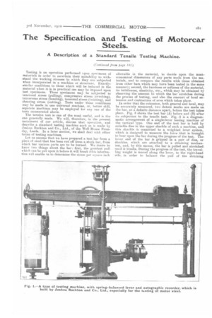
Such is the information obtainable with a simple testing machine. By means of micrometer measuring-devices, termed extensometers, more-detailed information regarding the elastic limit and the yield point may be obtained Full information as to the mechanical properties of the material can he obtained, and recorded automatically, on one of Buckton's machines, if it is provided with one of that maker's spring-balanced levers and autographic recorders; a machine so fitted is shown by a reproduced photograph (Fig. 1), whilst Fig. 4 is a scale drawing of the same machine. The test specimen is mounted between shackles, as already described, fur the single-lever machine, and the straining mechanism is next set in operation; the machine will then, without further attention,
inscribe upon a sheet of paper a permanent curve or diagram, which will show at a glance all the mechanical properties of the material under test. Fig. 5 shows a typical curve which was made on one of Buckton's machines; a detailed consideration of this chart will elucidate what we have already stated in the first instalment of this article, and will show the value of one's having a permanent record of the tensile test. The curve shown is inscribed by a pencil, which is given a vertical movement the extent of which is proportional to the load upon the specimen, and, therefore, the height of any point on the curve, measured from the base line, indicates the load at that, point. Horizontal lines may be ruled upon the paper, to represent loads to a calibrated scale. By reference to these lines, the loads are easily read off ; thus, as the curve at its highest point reaches the line for 23 tons, that is the maximum load which the specimen has withstood during the test. While the pencil is being moved vertically in proportion to the load, the cylinder around which the paper is wrapped is rotated, this rotation being equivalent to a horizontal movement of the paper, and the distance moved is at all times proportional to the extension of the specimen. The horizontal length of the curve, according to the calibrated scale, represents the amount which the specimen has stretched. The paper may be ruled with a number of vertical lines, by a reference to which the amount of the extension of the specimen for any given load may be ascertained.
Now that the general meaning of the curve has been explained, let us follow up its story in fuller detail. The curve starts at -the base line indicating no load, and rises sharply, indicating a gradual increase of the load, but with very-little stretch or extension until it nears the horizontal line for 15 tons. Up to that figure, the load has been below the elastic limit, and the specimen would return to its original length if the load were removed, or, a,s practical men say, it has taken no permanent set. It is only within this limit of stress that the material may safely be worked. Returning to the curve, it will be noted that, as the limit of elasticity is approached. the
curve begins to bend slightly until the yield point is reached. The material then suddenly takes a very-definite set, accompanied by a considerable weakening of the material, as shown by the downward movement of the curve (in the case of soft steel). A period of instability succeeds the change from the elastic to the " plastic" state of the material; the minimum load indicated during this period of instability is the true elastic strength of the material. From this point in the curve, the elastic limit having now been definitely passed, the specimen continues in a "plastic" state, and it goes on stretching under the influence of an increasing load. The curve soon begins to flatten considerably, until the specimen will stand no more load ; it then begins to break down in one place—to stretch locally. This local extension is accompanied by a moreor-less-marked decrease in the load-carrying power, and, finally, the material, not being able to stretch any further, breaks. Both the general and local extension of the specimen are indicated in Fig. 5, and, since the property of local extension indicates the material's capacity to resist impact and local injury, this part of the curve is very valuable.
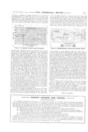
Fig. 6 shows some characteristic curves for various classes of material. In some of these, it may be seen that the elastic limit and yield point are practically identical, whilst many show no local extension. Joshua Buckton and Co., Ltd., of Leeds, is one of the foremost builders of tensile testing machines, and we are greatly indebted to that maker for the prints from which the drawings were prepared for the accompanying illustrations.
(To be continued.)