


With Intent to Improve.
Page 22
If you've noticed an error in this article please click here to report it so we can fix it.
A Weekly Summary of Recent Patents, of Interest to the Maker and User of Commercial Motor Vehicles.
Selected and Abridged by H. S. Hall, A.M.I.A.E.
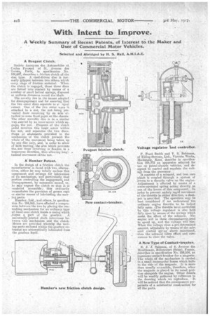
A Peugeot Clutch.
Societe Anonym() des Automobiles at Cycles Peihreet of 51, •Avenue des Terries, Parf's in speeification No.
• 100,687, describes a friction clutch of.the disc type. A steel-driven disc is normally gripped between two .others which • • carry rings of friction material. • When the clutch is engaged, these three diAcs are forced into "cantactby means of a number of small helical springs, disposed at uniform distances round the -Shaft.
The novelty lies in the mans adopted for disengagement and for ensuring that the two outer discs -separate to s' sepal
extent. One of the two outer 0.,..scs is attached to a nut the nut being prevented from revolving by An arm attached to some fixed point on the chassis. The other movable disc is in a similar way ,carried by An inneeiserew which engages. the .nut. Pressure of the clutch pedal revolves this inner screw within the nut, and separates the two 'discs. Stops or abutments . provided hi the mechanism of the clutch prevent the whole'of-the movement being taken up, hy one disc Only; and, in order to allow of both moving, the arm which prevents theoiut fromrevolving is flexible in a transverse direction, thus allowing longitudinal movement edi the nut.
A. Humber Patent.
in the design of a friction chitch the
• manufacturer is faced with two alternatives, either he may toeaily enclose this component and arrange for lubrication
. of its mechanism,' and particularly that portion controlling the engagementi and disengagement, by automatic means, or, ho iiaay expose the clutch so that it is reixlerod accessible; 'thisOrdinarily necessitates the provision of grease cups or similar means of lubricating the mov
• ing parts.
Iltunber, Ltd., 'and..othere, in specification No. 104,565. have effected a compromise between the two by placing the controlling-mechanism for an ordinary type of lined-cone clutch inside a casing which ...forms a part of the gearbox. A universally-jointed shaft intervenes between-this mechanism and the clutch. Means are prOvidecl whereby the MeV, ing parts enclosed within the gearbox extenslon. are automatically lubricated from the gearbox itself.
P. Frost Smith and V. S. Robinson, of Tilling-Stevens,. Ltd., Victoria Works, Maidstone, Kent, describe in specification 104,772 an apparatus adapted: for use on petrol-electric vehicles; and designed to control and regulate the voltage from the generator. .
It consists of a solenoid, and iron core which is coupled through a system n of levers to a throttle valve on the engiiie. Adjustment is effected by means of a screw-operated spring acting directly on one of the levers of this component. In order to prevent unduly rapid movement . of the throttle in either direction; a dash. pot is provided. The operation my be best considered if we understand the ordinary engine throttle to be loclied fully open, --The throttle lever controlled by this voltage Iregulator is also held fully open by means-of the springs which resist, the effect of the solenoid. The engine will in these circurnstaoces\tend to speed up, and the voltage will rise, When the voltage rises a pre-determined amount, adjustable by means of the sole-. noid control spring above mentioned, --then the solenoid takes effect and commences to close the valve.
A New Type of Contact-breaker.
hi: J. "J. Salm.son, of 9, Avenue des Moulineaax, Billancourt (Seine), Frande, describes in specification No. 104;554; in
• ingeniols contact-breaker for.a magneto. The whole d the nieehanism is carried_ in a small rectangular frame which bolts to the &Cieof the magneto. It is more than usnally accessible, therefore, when the magneto is placed in itS usual Posi-' tion alongside the engine. Other details will be readily gathered by reference to the drawing which we repioduco. It
will be noticed that the arrangement perpermits of a substantial construction for all the parts.