


High-speed Burst Chamber
Page 74
If you've noticed an error in this article please click here to report it so we can fix it.
20,000 R.P.M. POSSIBLE WITH NEW EQUIPMENT
A RECENT addition to the engineering ra test facilities of Automotive Products Co., Ltd., Leamington Spa, is a highspeed centrifugal burst chamber, designed in the research department and built and installed by the company's experimental department.
Burst and high-speed proving testshave been a feature of the firm's test programme for some time, particularly on Borg and Beck clutches, using equipment capable of providing speeds of up to 12,000 r.p.m., but this had limitations, both from the speed and size aspects, for future programmes. The new test chamber has, therefore, been designed for a maximum speed of 20,000 r.p.m., and is capable of accepting test pieces of up to 2-ft. diameter, with a limiting weight of approximately 150 lb.
For safety reasons, which are obvious when it is considered that during a test pieces of iron or steel, weighing anything up to 3 or 4 lb., leave the specimen at speeds approaching 250 m.p.h., the test specimen rotates in an adequately protected hole in the ground," and is driven by a vertical shaft.
Power for the equipment comes from a Standard Vanguard 2-litre engine and gearbox, flexibly mounted on a subframe, and driving a worm gear unit which converts the horizontal drive to a vertical one at an output pulley below the unit. Drive to the testing unit is transmitted through an endless belt, 3-in. wide and it -in. thick.
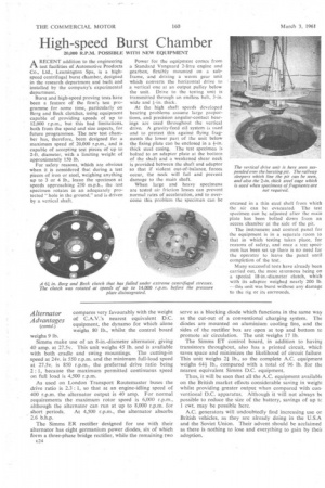
At the high shaft speeds developed bearing problems assume large proportions, and precision angular-contact bearings are used throughout the vertical drive. A gravity-feed oil system .is used and to protect this against flying fragments the lower part of the unit below the fixing plate can be enclosed in a thick steel casing. The test specimen is bolted to an adaptor plate at the bottom of the shaft and a weakened shear neck is provided between the shaft and adaptor so that if violent out-of-balance, forces occur, the neck will fail and prevent damage to the main shaft.
When large and heavy specimens are tested air friction losses can prevent normal rates of acceleration, and to overcome this problem the specimen can be encased in a thin steel shell from which the air can be evacuated. The test specimen can be adjusted after the main plate has been bolted down from an access chamber at the side of the pit.
The instrument and control panel for the equipment is in a separate room to that in which testing takes place, for reasons of safety, and once a lest specimen has been set up there is no need for the operator to leave the panel until completion of the test.
Many successful tests have already been carried out, the most strenuous being on a special 18-in.-diameter clutch, which with its adaptor weighed nearly 200 lb. —this unit was burst without any damage to the rig or its surrounds.