


ALTER1 ADVAN7
Page 66
Page 67
Page 68
Page 73
Page 74
If you've noticed an error in this article please click here to report it so we can fix it.
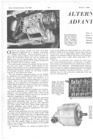
ONE of the hardest worked—and often most sadly neglected—components in a modern commercial vehicle is the battery. This is particularly so in the case of public service vehicles, some current examples of which rely on electrical power not only for starting and
lighting, but also for gearchanging, door operation and even advertising display panels, not to mention installations such as heaters and—in coaches—radios.
It is small wonder, therefore, that despite the big advances that have been made in battery design during the last decade, battery failure can be a pressing problem for many operators, besides being a headache for designers in respect of providing adequate stowage for the large batteries required to meet present-day needs.
That this somewhat depressing picture can be changed by significant, but nevertheless miraculous, little devices known as semi-conductor diodes and transistors is a remarkable testimony to the practical application of modern science. Yet it is the semi-conductor which is making it possible for A.C. generators to be installed in commercialvehicle chassis, installation which would have been impracticably bulky, heavy and expensive with the rectifying equipment available a few years ago.
As it is, by using semi-conductor rectifiers and transistorized control equipment, A.C. installations may easily be applied to new and existing vehicles with a direct saving in weight, a foreseeable saving in cost and an increase in efficiency, depending on alternator design.
The potential success of alternating-current generating systems arises from one basic deficiency of the D.C. gener ators almost universally used on road vehicles. This deficiency is that the maximum speed of a D.C. generator can rarely exceed 5,000 r.p.m., above which speed com mutation difficulties arise, which lead to rapid brush deterioration, high commutator temperatures and excessive brush-contact losses.
Because of this speed limit the ratio of the drive between the engine and the dynamo has to be based on this 5,000 r.p.m. maximum, which means that at engine-idling speed the dynamo is rotating so slowly that its current output is insufficient to feed the battery. As public service vehicles nowadays spend a high proportion of their operational time with their engines idling, it follows therefore that battery over-working and under-charging are unavoidable evils of a D.C. system.
An alternator, however, can operate at speeds well in
excess of the 5,000-r.p.m. limit imposed on a D.C. unit— speeds of 10,000 r.p.m. are feasible—thus its drive ratio can be such that even at engine-idling speed a high currentoutput can be obtained, whilst in any case an A.C. generator provides output over a wider speed range than a D.C. generator.
This fact has obviously been realized for many years and—as any school-boy knows—an alternator is a lighter, more compact and considerably more simple piece of equipment than a D.C. generator. Alternating current, however, cannot be used to charge a conventional battery, although it can, of course, be used for lighting purposes. For vehicle applications, therefore, conversion of the A.C. to D.C. is essential, and it is this conversion (rectifying) which has been the stumbling block. Thus, the 30 per ceat. crease in generating pacity which it has en proved is necessary )r the modern Lssenger vehicle in. ggy weather (accenated low-speed condiHis) is available without having to resort to the developent of new and larger types of D.C. generator.
The advantages of A.C. generating systems can be mmed up as follows, therefore. They are easy to apply existing vehicles—in many cases easier than lowerpacity D.C. units; there is a reduction in weight and Ilk; the battery -can be charged constantly, irrespective engine speed; the equipment involved is more simple pith a transistorized control board the only moving comment is the generator rotor); battery life is extended; ialler—and therefore lighter—batteries can be used for the me function; and the overall life of all the units should be eater than that of the components of a D.C. system.
As it is so rare these days to get anything for nothing, it easy to imagine people -interested in A.C. equipment saying, " Ah, but what about the price?" For a change, the initial cost involved with sOme A.C. units is already under 5 per cent, greater than that of the nearest equivalent D.C. gear—which, size for size, would not provide the same output in any case. Once electrical manufacturers are able to put the equipment into quantity production (which presents no problems once sales are assured) a complete A.C. set should be cheaper than existing D.C. sets.
So much for the price question. As to the potential market, this is by no means restricted to passenger vehicles. Police cars, fire appliances, ambulances and taxis are all vehicles normally fitted with two-way radio apparatus which helps to add to the load on the vehicle battery. Stop-andstart delivery vans—particularly those with illuminated name boards—are also vehicles which subject their batteries to heavy loadings, whilst yet another series of applications is to be found on agricultural and forestry vehicles, including -powering hand toots.
Police cars provide an interesting example of light vehicles requiring excessive electrical power. Not only do these vehicles have the normal lighting and starting systems, but additional equipment includes interior heaters, "Police " signs, bells, loud-hailers and two-way radio. Many police cars have already been equipped with A.C. generating gear, those with D.C. having to incur the penalty of carrying two batteries to cope with the maximum likely loadings.
With most A.C. generating sets three separate pieces of equipment are required—alternator, rectifier and control board—although the Lucas equipment for cars and light vans combines the rectifier with the alternator, and this is a development likely to take place soon on higher-capacity alternators, so simplifying the equipment even further.
There are three types of alternator—the inductor, the salient-pole and the imbricated-pole types—but only the imbricated-pole alternator is employed on British vehicles. Whilst, on the face of it, the inductor alternator would appear most attractive from the production viewpoint because of its lack of slip-rings and because it has both field and output windings on the stator and only laminated pole projections on the rotor, it has one serious disadvantage in that the flux embracing one output coil changes only from zero to maximum, and does not reverse -as in the excited-rotor alternator.
Therefore the inductor alternator can provide only half the voltage of an excited-rotor machine with the same flux density in the air gap, consequently the volume of the machine would have to be comparable with that of the D.C. generator it was designed to replace.
Because the vibrating-contact regulators at present in use with D.C. systems can handle a maximum of only 2 amp. at 24., such regulators could not be used with salient-pole alternators, but they can be used without modification to control the field current of imbricated-pole machines, the value of which would be 1.5 amp. compared with, say, 5 amp. for the salient-pole type. Even the use of transistorized regulators, which can deal with greater field currents, would still not necessarily lead to the adoption of salient-pole equipment because an imbricated-pole generator is the cheaper of the two to produce.
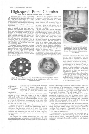
Imbricated-pole Rotor
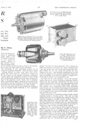
The construction of a typical imbricated-pole rotor can be seen from the photograph on page 157. The two identical rotor claws, which can be either cast or forged, are attached to the core by short bolts and completely enclose the field coil. These two claws and the tubular core, which is shrunk on to the shaft, comprise the magnetic circuit of the rotor.
The stationary yoke or stator contains the heavy-current windings of the alternator, these being equivalent to those in the armature of a D.C. generator. Because these windings are stationary, however, the current generated in them can be fed directly to the output terminals—a very much more simple and trouble-free course than that applying to the commutator of a D.C. machine.
Similarly, by this construction, heat generated in the windings is easier to dissipate, giving rise to cooler running E I 8
conditions, whilst in any case the A.C. unit is not subject to the temperature-rise limitations imposed by the col mutator and its soldered connections in a D.C. generati There are only two electrical connections between t slip rings and field coils in an A.C. machine, and these c be effected by brazing. Brazing can be employed at t connections between the copper strips in the stator win ings also, so the maximum permissible temperature f the windings of a totally enclosed alternator is often limit only by the 'temperature which would melt the grease the bearings.
Forced Cooling
Many alternators of a size suitable for heavy-vehi( applications have a built-in fan to force cooling air throu the interior of the machine. To avoid the possibility the slip rings becoming dirty, they can be located in enclosed compartment outside the ventilated body of t machine. The output of an alternator can be changed cc siderably according to the amount of ventilation provid( a through-ventilated machine producing up to twice t current of a completely unventilated unit.
Alternators can be expected to show appreciable savin in maintenance costs compared with equivalent D. generators, a major item in the overhaul of the latter ty of equipment being commutator skimming and bru renewal. The deposition of carbon in the interior of D.C. unit lowers the insulation resistance and this in its presents a major cleaning problem, all of which are troub to which an alternator is not liable.
Although alternators were used on Model T Fords, tl vehicle had no battery and therefore its lights and so foi obtained alternating current directly from the generat This layout was admirable for its simplicity as it eliminal the need for a rectifier. Unfortunately, batteries are tu indispensable, therefore a rectifying unit is an essential it in any alternating-current system.
As alternators used in vehicles are wound for thn phase operation, the rectifiers employed are three-pha full-wave units with six, or multiples of six, rectifier ce for which semi-conductors are invariably employed. There is a choice of three materials for these semiconductors: selenium, germanium and silicon, the material employed depending upon ambient temperature, ventilation, space availability and initial cost.
Although selenium suffers from a few disadvantages, the bulkier design of a selenium unit gives greater heat capacity and the ability to tolerate over-currents and high temperatures for short periods. This type of rectifier is used by C.A.V., Ltd., whose RUS-6 rectifier contains six dry-plate selenium elements.
Simms Motor Units, Ltd., employ germanium diodes in their rectifier, whilst rectification in the case of the smaller Lucas equipment is carried out by silicon diodes built into the slip-ring end of the alternator and cooled by the air how through the machine.
Silicon units can operate at higher temperatures than germanium and selenium equipment and they are not subject to ageing. Furthermore, their weight and size are less, but they cost almost twice as much to manufacture as selenium units.
Undoubtedly, silicon is the best of the three available materials, particularly where high-ambient temperatures are likely to be encountered, whilst another big advantage of this material is that a rectifier incorporating it can usually be mounted directly on the alternator itself, thereby permitting the alternator to be connected directly to the battery.
As with conventional D.C. systems, some means has to be provided of regulating the D.C. output from the rectifier to suit the demands of the battery. A conventional vibratory-contact type of regulator can be employed, but the use of transistorized regulators confers the advantage of the elimination of contacts and moving parts, and both C.A.V. and Simms offer this type of regulator.
An alternative type of regulator forms in effect a combination of these two systems, and this is favoured by Joseph Lucas, Ltd., whose control box contains a vibratingcontact regulator to control the alternator field current (and hence the output voltage), and a transistor because the held circuit of most alternators is more inductive than that of a D.C. machine and so any direct making and breaking of this circuit by vibrating contacts would involve contact ourning and oxidization.
By using a transistor, the vibrating contacts are called upon to handle only a small non-inductive pilot current while control of the main held is exercised by the transistor.
With a full transistor control board, such as the Simms ET unit, the voltage setting at which the system operates is dependent upon the proportion of the generated voltage which is applied to a Zener diode, this proportion being initially adjustable by use of a potentiometer. Current regulation is obtained via the voltage-regulation circuits, but is triggered by using the forward characteristic of a germanium diode made responsive to the voltage developed across a low resistance in the main current circuits.
The three manufacturers of vehicle alternator systems in this country—C.A.V., Lucas and Simms—have all chosen different sizes of generator—the smallest being the Lucas 12v, 6-in.-diameter unit.
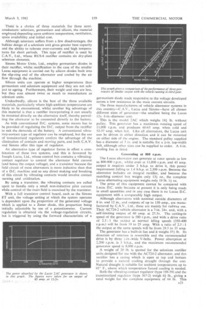
This is the model 2AC which weighs 181 lb. without pulley. This genera tor has a maximum running speed of 11,000 r.p.m. and produces 60-65 amp, when cold and 52-57 amp. when hot. Like all alternators, the Lucas unit can be driven in either direction and it can be mounted on either side of the engine. The standard pulley supplied has a diameter of 3 in. and is suitable for a i-in, top-width belt, although other sizes can be supplied to order. A 6-in. cooling fan is fitted.
Generating at 800 r.p.m.
The Lucas alternator can generate at rotor speeds as low as 800-900 r.p.m., whilst even at 11,000 r.p.m. and 45 amp. output it requires under 2 b.h.p. to drive it, this power requirement falling to 1.4 b.h.p. at 2,500 r.p.m. Because the alternator includes an integral rectifier, and because the matching control box weighs only 131 oz., the complete Lucas alternating equipment weighs only 19 lb. 1i oz.
The price of this equipment cannot be compared with Lucas D.C. units because at present it is only being made in small quantities and in any case there is no Lucas D.C. equipment with a comparably high output.
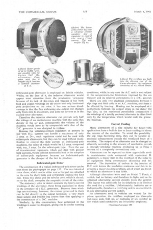
Although alternators with nominal outside diameters of 8 in. and 12 in., and outputs of up to 150 amp., are manufactured by C.A.V., Ltd., these are mainly, for railway use. Their AC724-2 vehicle alternator is a 7-in, 24v, unit, with a self-limiting output of 60 amp. at 27.5v. The cutting-in speed of the generator is 580 r.p.m., and with a drive ratio of 2.3 : 1 the output at normal idling speeds (350-400 r.p.m.) will be from 19 to 25 amp. With a ratio of 2.5 : 1 the output at the same speeds will be from 29.5 to 35 amp.
The generator has a built-in fan and it weighs 371 lb. Its direction of rotation is reversible and the recommended drive is by three -I-in.-wide V-belts. Power absorption at 2,200 r.p.m. is 3 b.h.p., and the maximum recommended generator speed is 8.000 r.p.m.
A weight of 20 lb. is quoted for the •selenium rectifier units designed for use with the AC724-2 alternator, and this rectifier has a casing which is open at top and bottom to provide a natural cooling draught through the unit. Natural draught is suitable for ambient temperatures up to 95° F., above which temperature forced cooling is needed.
Both the vibrating-contact regulator (type 189-59) and the transistorized regulator (type 367-2) weigh 6i lb., giving a total weight for the complete equipment of 64 lb. This compares very favourably with the weight of C.A.V.'s nearest equivalent D.C. equipment, the dynamo for which alone weighs 80 lb., whilst the control board weighs 9 lb.
Simms make use of an 8-in.-diameter alternator, giving 40 amp. at 27.5v. This unit weighs 45 lb. and is available with both cradle and swing mountings. The cutting-in speed at 24v. is 550 r.p.m. and the minimum full-load speed at 27.5v. is 850 r.p.m., the preferred drive ratio being 2 : 1, because the maximum permitted continuous speed on full load is 4,500 r.p.m.
As used on London Transport Routemaster buses the drive ratio is 2.3 : 1, so that at an engine-idling speed of 400 r.p.m. the alternator output is 40 amp. For normal requirements the maximum rotor speed is 6,000 r.p.m., although the alternator can run at up to 8,000 r.p.m. for short periods. At 4,500 r.p.m., the alternator absorbs 2.6 b.h.p.
The Simms ER rectifier designed for use with their alternator has eight germanium power diodes, six of which form a three-phase bridge rectifier, while the remaining two E24 serve as a blocking diode which functions in the same way as the cut-out of a conventional charging system. The diodes are mounted on aluminium cooling fins, and the sides of the rectifier box are open at top and bottom to promote air circulation. The unit weighs 17 lb.
The Simms ET control board, in addition to having transistors throughout, also has a printed circuit, which saves space and minimizes the likelihood of circuit failure. This unit weighs 21 lb., so the complete A.C. equipmeni weighs 641 lb., compared with a total of 96 lb. for the nearest equivalent Simms D.C. equipment.
Thus, it will be seen that all the A.C. equipment available on the British market effects considerable saving in weight whilst providing greater output when compared with conventional D.C. apparatus. Although it will not always be possible to reduce the size of the battery, savings of up tc 1 cwt. may be possible here.
A.C. generators will undoubtedly find increasing use or British vehicles, as they are already doing in the U.S.A and the Soviet Union. Their advent should be acclaimed as there is nothing to lose and everything to gain by then adoption.