


A Road-Rail Vehicle
Page 64
If you've noticed an error in this article please click here to report it so we can fix it.
A Résumé of Recently Published Patent Specifications
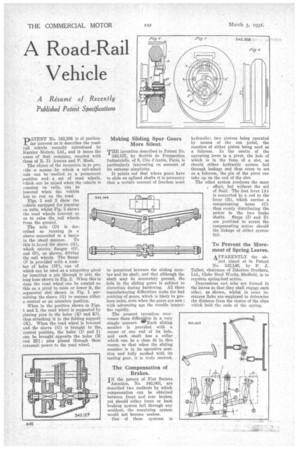
Thp ATENT No. 342,108 is of particu lar interest as it describes the roadrail vehicle recently introduced by Karrier Motors, Ltd., and it bears the name of that company, coupled with those of B.. D. Averns and P. Meek.
The object of the invention is to provide a means by which a rail-wheel axle can be -carried in a permanent position and a set of road wheels, 'which can be raised when the vehicle is running on rails, can • he
lowered when the vehicle has to run on the road.
Figs. 1 and 2 Show the vehicle equipped for running on rails, whilst Fig. 3 shows the road wheels lowered so as to raise the rail wheels from the ground.
The axle (D) is described as running in a sleeve connected to a banjo in the Mal manner. To this is keyed the sleeve (G), which carries flanges (GI, and 02), as shown, driving the rail wheels. The flange 02 is .provided with a number of holes (112), one of which can be used as a temporary pivot by inserting a pin through it into the long boss shown in Fig. 2. When this is done the road wheel can be rotated on this as a pivot to raise or lower it, the segmental slot shown in Fig. 1 permitting the sleeve (0) to assume either
a central or an eccentric position. •
When in the position shown in Figs. 1 and 2, the road wheel is supported by Placing pins in the holes (Kt and K2), thus attaching it to the folding support (K). When the road wheel is lowered and the sleeve (0) is brought to tha,
central position, the holes and I)' can be brought opposite the holes (H and Hi) ; pins placed through them transmit power to the road wheel.
Making Sliding Spur Gears More Silent.
THE invention described in Patent No. 342,127, by Socike de Prospection Industrielle, of 8, Cite d'Antin, Paris, is particularly interesting on account of its extreme simplicity.
It points out that where gears have to slide on splined shafts it is necessary that a certain amount of freedom must be permitted between the sliding member and its shaft, and that although the shaft may be accurately ground, the hole in the sliding gears is subject to distortion during hardening. All these manufacturing difficulties make for bad centring of gears, which is likely to produce noise, even when the gears are new ; with advancing age the trouble intensifies rapidly.
The present invention overcomes these diffic&ies in a very simple manner. INFEach sliding member is provided with a recess at ,one end of its bole, and each shaft has a collar which can be a close fit in this recess, so that when the sliding member is in its operative position and fully meshed with its mating gear, it is truly centred.
The Compensation of Brakes.
IN the patent of Fiat Societe Anonima, No. 342,063, are described two methods by which compensation can be obtained between front and rear brakes, yet she'd(' either front or back braking system fail through any accident, the remaining system would not become useless.
One of these systems is
hydraulic; two pistons being operated by means of the one pedal, the reaction, of either piston being used as a fulcrum. In the centre of the operating lever is a pivot, the hole of which is in the form of a slot, so should either hydraulic system fail through leakage and thus cease to act as a fulcrum, the pin of the pivot can take up on the end of the slot.
The other system produces the same , effect, but without the aid of fluid. The foot lever (A) is connected by a rod to the lever (B), which carries a compensating beam (C) thus evenly distributing the power to the two brake shafts. Stops (D and E) are provided to arrest the compensating action should the linkage of either system fail.
To Prevent the Movement of Spring Leaves.
APPARENTLY the ob
ject aimed at in Patent No. 342,146, by F. J. Talbot, chairman of Ibbotson Brothers, Ltd, Globe Steel Works, Sheffield, is to regulate spring-leaf action.
Depressions and nibs are formed in the leaves so that they shall engage each other, as shown, whilst in some instances links are 'employed to determine the distance from the centre of the clips which hold the ends of the spring.