


Further Pointers from
Page 54
Page 55
Page 56
If you've noticed an error in this article please click here to report it so we can fix it.
THE BERLIN SHOW
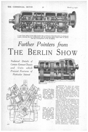
A MONGST the many new engines tiproduced in Germany for commercial purposes, perhaps those which possess the greatest novelty are the 12-cylindered Maybach, arranged in V form, and the 12-cylindered Henschel, in which the cylinders are in one block of 12 arranged in parallel pairs; the latter unit being the more unusual, we will deal with it first.
It is obvious that some special means must be employed for positioning, the cylinders in the manner indicated, and winch is shown in the cross-sectional drawing on the next page. This is achieved by utilizing two distinct crank-shafts geared together by double-helical pinions and operating a single camshaft situated centrally. The phasing is such that the centre lines of the crankshafts can be much closer together than the sum of the respective crank throws, and this is clearly shown in the illustration which heads this article, where also can be seen the timing gear and the piping for the pressure-fed lubricating oil.
This .remarkable engine actually develops 250 b.h.p., and utilizes two separate dynamos and coil-ignition sets, and two carburetters. All the ,valves are overhead and are operated by tappet rods which are comparatively short because of the high level of the camshaft.
The Maybach unit is a development from the 12.cylindered engine used on the Graf Zeppelin. Each cylinder has a bore of 92 mm. and the stroke is 100 mm., the total displacement being 7,978 c.c., resulting in a power development of 150 b.h.p. at 2,300 r.p.m. This might seem a fairly high speed for such a large engine, but it is not excessive, the piston speed being comparatively low
owing to the short stroke. The angle between the cylinders is 60 degrees and, owing to the arrangement, the essential form of standard crankshaft as used on a six-cylindered engine has been preserved. The overall dimensions are small and there is no increase in the length of the unit over that required for six-cylinde red engine developing 100 b.h.p.
A compression ratio of 6.3 to 1 is utilized. Both the upper and lower halves of the crankcase are of light alloy. The cylinders are also of light metal with cast-iron liners, and the valves are overhead, being operated by a single camshaft carried in seven bearings. Eight white-metal bearings support the crankshaft, whilst the whole unit is three-point mounted on rubber cushions.
The battery is fed by a 400-watt dynamo, and there are two Bosch distributors. Two Solex double carburetters supply the mixture. The fuel consumption is claimed to be .53 lb. per b.h.p.hour, and the oil consumption from .009 to .013 lb. per b.h.p.-hour. Noiseless gearing is exclusively employed for driving the auxiliaries, thus obviating the need for periodical readjustment.
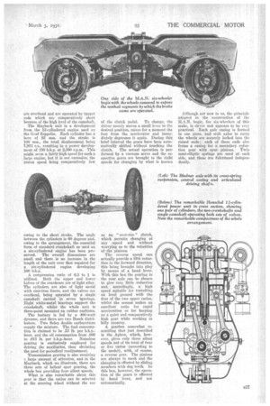
Transmission gearing is also receiving r. large amount of attention, and in the Maybach, which we illustrate, there are three sets of helical spur gearing, the whole box providing four silent speeds.
What is also remarkable about this gear is that the ratios can be selected at the steering wheel without the use of the clutch pedal. To change, the driver merely moves a small lever to the desired position, raises for a moment the foot from the accelerator and immediately depresses it again. During this brief interval the gears have been automatically shifted without touching the
clutch. The actual operation is performed by a vacuum servo and the respective gears are brought to the right speeds for changing by what is known
as an " over-rim " clutch, which permits changing at any -speed and without worrying as to the velocities ofthe pinions.
The reverse speed can actually provide a fifth reduction in the forward direction, this being brought into play by means of a hand lever. With this box the gearing in the rear axle can be chosen to. give very little reduction and, accordingly, a high speed suitable 'for travelling on level ground with the first of the two upper ratios, whilst the second makes an excellent ratio for rapid acceleration or for keeping on a quiet and comparatively high gear while working in hilly country.
A gearbox somewhat resembling that just described is the Aphon, which, however, gives only three silent speeds out of its total of four or five ratios (according to the model), with, of course, a reverse gear. The pinions are always in mesh and the changing is effected by sliding members with dog teeth. In this box, however, the operation of the gears is effected by hand lever, and not automatically.
Although not new to us, the principle adopted in the construction of the M.A.N. bogie, for six-wheelers a this make, is clever and appears to be very practical. Each axle casing is formed in one piece, and stub axles to carry the wheels are securely locked into the raised ends ; each of these ends also forms a casing for a secondary reduc
tion gear with spur pinions. Twin semi-elliptic springs are -used at each side, and these are fuleramed independently.
Our illustration shows another unusual feature of the design. This is the means for operating the brakes. It will be seen that passing through the centre of each hub is a spindle carrying a toothed segment which meshes with a similar segment mounted on the spindle of the shoe-expanding cam.
In the first part of this article which we published last week we referred to the increasing use of articulated axles, and we now illustrate a further example, which is the product of August Blodner, of Gotha, Germany. Such in axle earl he used for both front and rear-wheel drives, and this maker supplies corresponding axles with fixed or steering
hubs for use in the same connection. The final-drive .gear is carried in a central casing which is rigidly secured to the centre bracket supporting the single. cross-spring, whilst shafts with universal joints at each end take the drive to the wheels.
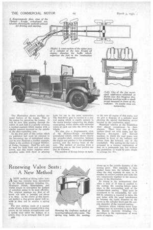
We also give a diagrammatic view of the Flettner-Krupp ten-wheeled articulated vehicle, which shows clearly the propeller-shaft connection between the engine and gearbox in the articulated portion; and the driving bogie at the rear. The method of steering from a projecting arm on the front portion can also be followed.
The mention of Krupp brings us again to the new oil engine of this make, and we give a diagram of a cylinder head _showing the sbecial fuel-heating device carried in the combustion space.
Municipal vehicles at the Exhibition were almost conspicuous by their absence. There were two or three trailers fitted out with tanks, and the Itlagirus fire-engine and first-aid machine, in which the neat pump was mounted in front of the radiator and driven from the forward end of the crankshaft. The seating for the crew is arranged in a manner reminiscent of that on a promenade bus, but without any protection ; it would be quite simple to arrange for this