


A NEW BRITISH FUEL PUMP FOR OIL ENGINES
Page 50
Page 51
Page 52
If you've noticed an error in this article please click here to report it so we can fix it.
AYEAR ago we described the initial type of Benes fuel pump; since then it has undergone various changes and has had certain new and practical 'features grafted into its design so that a description of the new model will be of interest to the many who are concerned with oil engines. To-day they number some thousands and the fu e; pump is the most vital factor in oil-engine efficiency.
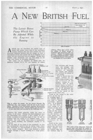
The pump can be supplied by Benes, Ltd., 24,Holborn, London, E.C.1, for any number of engine }kw to adjust the pump; the key passes through the calibrated disc and engages with the slot in the control sleeve. Rotation of the iast.named regulates the quantity of fuel delivered per stroke. Known settings may be restored or new ones tried and recorded by the calibrated disc.
cylinders, the pump principle being the same, of course, in all cases. Taking the four-cylindered type the dimensions are:—length, 8 ins.; height, Si ins.; width (exclusive of mounting lugs), 3 ins. It will be realized that the casing is of compact form. Incidentally, the very latest types have a horizontally Plit casing, enabling the camshaft rapidly to be removed.
In the base of the pump is the camshaft; as this has symmetrical cams it can be driven from either end, clockwise or anthclockwise—a great advantage to the engine designer. Each cam operates a pump plunger through a tappet working in a large guide;
3332
this obviates side thrust upon the plunger and makes for long life and accuracy of metering. The tappet and plunger are returned by means of a coil spring.
Fuel is forced into the engine cylinder by the rising pump plunger ; par tial rotation of the plunger, acting in con junction with a fixed, ported sleeve, in which it works, regulates the quan tity of oil delivered per stroke, therefore it con Fixed in the casing i sleeve; at the top of its working space is the vertical delivery port with a simple non-return delivery valve. It is possible to use this form of valve owing to the absence of any tendency to dribbling action of the punip. Drilled horizontally are the suction and relief ports, both in communication with the annular suction chamber in the casing.
Fixed in the outer sleeve is the ported sleeve, the two ports being shaped with one vertical edge and one inclined edge in
each cas.?.. The third sleeve is for control purposes. It can be rotated, by means of the rack, around the outer sleeve; by reason of vertical slots mating with MO on the plunger it can impart a partial turn to the plunger while the latter is rising or
In -addition to the rack genr for engine-speed control, each sleeve can be synchronized or tuned ; this fine adjustment can be carried out, if necessary, while the engine is running. Comparative settings can be coAnined immediately and recorded, and previous settings restored by use of the separate tool and calibrated disc, as shown in one of the accompanying illustrations.
At the lop of the plunger is a vertical hole communicating with one drilled through the diameter, about onethird of the length from the top.
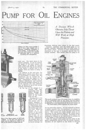
Turning now to the action of the pump, this matter will be greatly simplified by reference to the series of illustrations showing diagrammatically the suction and injection cycle. When the plunger is at the bottom of the stroke the space. above it i. full of fuel. As the plunger rises so does the oil; immediately the plunger seals the suction ports the fuel is forced .through the non-return delivery valve above, to the fuel nozzle.
Injection continues until the radial ports of the plunger establish connection with the relief ports in the ported sleeve. Pressure is then instantaneously destroyed as the fuel is by-passed directly into the suction chamber. This obtains when the pump is set This partly sectioned view of the pump shows its simplicity and, in conjunction with the text, makes dear the method of operation. In the latest type of instrument the control arm is replaced by a rack mechanism for the partial rotation of the control sleeve, which regulates the engine speed.
for the full-stroke position. If it be required to deliver a smaller quantity than the maximum, the plunger is rotated slightly by means of the rack gear and control sleeve. This causes the radial plunger ports to be uncovered by the inclined edges of the ported sleeve before the completion of the stroke. According to the earliness or lateness of the destruction of pressure so is the volume of fuel delivered per stroke.
Both the plunger relief ports and the ports in the sleeve communicate directly with the suction chamber, therefore oil not required on any stroke is returned 533 to the suction chamber without waste, while the least possible resistance is thereby offered to the flow of the by-passed fuel. When the plunger is turned so that its relief ports coincide with the bases of the openings in the ported sleeve, no fuel can be delivered and the engine stops.
A study of the design and working-principles shows that the ends of the injection period are definite, i.e., no dribbling is caused, owing to the rapidity with which pressure is destroyed, there is no unequal side pressure upon the plunger—a very important point— and injection pressures up to, and exceeding, 300
90 March 3, 193!„4:
atmospheres can be obtained and maintained for unusually long periods, owing to the unbroken cylindrical surface of. the Plunger, and equalized radial pressure eliminating wear.
The curves show plungers Nos. 7 and 8 specially lapped to correspond with wear resulting from about three years' working, the clearance in these being three times that of the others, but the pressure does not fall below 200 atmospheres after standing for an hour. It is claimed that instantaneous starting from cold is made possible, and this without pre-heating, or the use of heater plugs, etc.
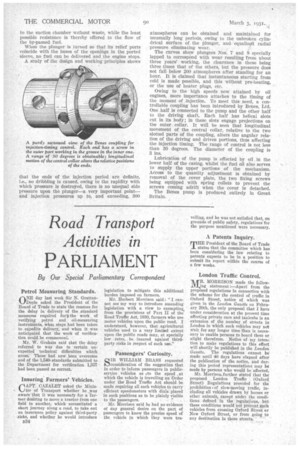
Owing to the high speeds now attained by oil engines, more importance attaches to the timing of the moment of injection. To meet this need, a controllable coupling has been introduced by Belles, Ltd. One half is connected to the pump and the other half to the driving shaft. Each half has helical slots cut in its body; in these slots engage projections on the outer collar. It will be seen that longitudinal movement of the central collar, relative to the two slotted parts of the coupling, alters the angular relation of the driving and driven portions, thus affecting the injection timing. The range of control is not less than 30 degrees. The diameter of the coupling is
• Sins.
Lubrication of the pump is effected by oil in the lower half of the casing, whilst the fuel oil also serves to supply the upper portions of the mechanism. Access to the quantity adjustment is obtained by removal of the cover plate, the two fixing screws being equipped with spring collets to prevent the screws coming adrift when the cover is detached. The Benes pump is produced entirely in Great Britain.