


Patents Completed.
Page 22
If you've noticed an error in this article please click here to report it so we can fix it.
Complete specifications of the following patents will be sent to any address in the United Kingdom upon receipt of eightpence per copy at the Sale Branch, Patent Office, Holborn, W.C.
EXCESS SPEED INDICATOR. — Hounsfield.—No. 2,363, dated 1st February, 1909.—This invention relates to speed indicators of the type in which an audible alarm is sounded when the predetermined speed of a motor vehicle is exceeded. A spindle carrying a cylindrical easing is mounted in ball bearings so as to be easily rotatable. This spindle is connected with the cardan shaft or with any other moving part of the motor, the speed of which is proportional to that uf the vehicle. The cylindrical casing is provided with extensions to which are pivoted governor aims, the latter carrying strikers which are lousely mounted on pins screwed into the governor arms. Within the cylindrical casing, a dashpot is arranged having a central tubular stem which accommodates a spiral spring that tends to maintain the dashpot in its raised position. This tubular stem has a flange, upon which two arms rest, these arms being rigid with the pivots of the governor arms so that they move with them. In close proximity to the strikers, a gong is arranged, and this latter is sounded on a predetermined speed's being exceeded. The dashpot preferably moves in a. bath of oil or other fluid. An adjustable stop is provided to limit its downward movement, and thus to prevent the governor arms becoming damaged owing to the latter swinging outwardly too far. The ten$ion of the spiral spring within the dashpot is also capable of adjustment, so tint the speed at which the device operates can be varied. A suitable casing wick sea the whole of the mechanism.
HAND TOOL-HOLDER. — ButlerLloyd.—No. 5,933, dated 12th March, 199.—This invention relates to a toolholder for hand tools such as screwdrivers, box-spanners and the like. The handle comprises two tubular members jointed by links. Within each of the tubular members, a spindle is arranged which is free to rotate therein, hut which is prevented from sliding longitudinally by a set-screw engaging a groove formed in the spindle. These spindles are provided with toothed heads, the teeth of which are constantly in mesh. The teeth on the heads are so cut as to allow the spindles to be moved angularly with relation to one another, without disengaging the teeth, so that the spindles may revolve within the tubular members at
any angle. The tubular members are cut away on one side to permit their being turned on the links at right angles to one another, and stops are provided to limit this angular movement,. One spindle is provided with a set-screw for heading the screw-driver or other tool, and the other spindle is fitted with a handle. In use, the tubular members may be gripped by one hand and the handle turned with the other hand.
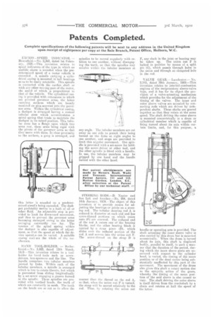
STEERING RODS.—D. Napier and San Ltd. and Another—No, 994, dated 14th January, 1909.—The object of this invention is to provide means for adjusting the bearings or joints on a steering rod. The tubular steering rod A is reduced in diameter at each end and has screw-thread portions on which union nuts 01 are screwed. The reduced end of the rod A enters one of the bearing blocks, and the other bearing block is carried by a strap piece (1)1, which slides over the reduced portion of the rod A and screws into the union out F. The screw-thread on the strap D is
coarser than the thread on the rod A, so that. when the union nut F is turned, the strap will be moved relatively to the rod. Thus, by rotating the union nut F, any slack in the joint or bearing may be taken up. The union nut F is locked in position by means of a split pin (0), which passes through bolos in the union and through an elongated hole in the rod.
VALVE GEAR.— Latichester.— No. 2,145, dated 29th January, 1909.—This invention relates to internal-combustion engines of the reciprocatory sleeve-valve type, and it has for its abject the provision of a valve-actuating mechanism which provides for the adjustment of the timing of the valves. The inner and outer sleeve valves are actuated by connecting rods which are driven by independent shafts. These shafts are geared together so that they rotate at the same speed. The shaft driving the outer sleeve is mounted concentrically in a drum or cylindrical member which is capable of being turned about its axis within certain limits, and, for this purpose, a
her die or operating arm is provided. The shaft actuating the inner sleeve valve is also carried by this drum but is mounted eccentrically. When the drum is turned about its axis, this shaft is displaced bodily, parallel to itself, in such a manner that the duration of the period, during which the inner sleeve ports are uncovered with respect to the cylinder head, is varied, the timing of the mean position or of the dead centre being substantially unaffected by this part of the movement. The movement of the drum also gives this shaft a rotary motion due to the epicyclic action of the gears, whereby the timing of the mean position of the said sleeve is also caused to vary. The shaft driving the outer sleeve is itself driven from the crankshaft by a chain and rotates at half the speed of the latter.