


Injection Nozzle Gives Pilot Injection..
Page 26
If you've noticed an error in this article please click here to report it so we can fix it.
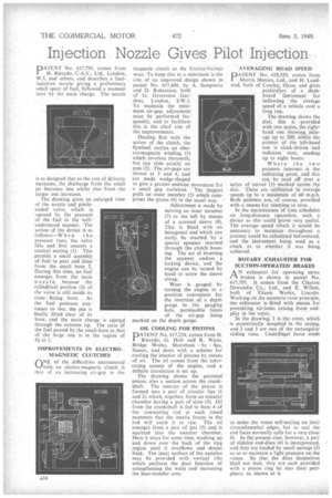
PATEN T No. 617,795, comes from H. Ricardo, C.A.V.; Ltd., London, W.3, and others, and describes a fuel injection nozzle giving a preliminary small spurt of fuel, followed a moment liter 13S, the main charge. The nozzle
is so designed that as the rate of delivery increases, the discharge from the small jet becomes less whilst that from the larger one increases.
The drawing gives art enlarged view of the nozzle and pintle ended valve, which is • opened by the pressure of the fuel in the wellunderstood manner. The action of the device is as h e n t he pressure rises, the valve lifts and first unseals a conical seating (1). This pertnits a small quantity of fuel to pass and issue from the small bore 2. During this time, no fuel emerges from the main nozzle, because the cylindrical portion (3) of the valve is still inside its
close fitting. bore. As the fuel pressure continues to rise, the pin is finally lifted clear of its bore, and the main charge is ejected through the extreme tip. The ratio Of the fuel passed by the small bore to that of the large one is in the region of 6i to 1.
magnetic circuit as the friction-facings wear. To keep this to a minimum is the aim of an improved design shown in patent No. 617,406, by A. Sampietro and D. Robertson, both of la, Grosvenor Gardens, London, S.W.I. To maintain the minimum air-gap, adjustment must be performed frequently, and to facilitate this is the chief aim of the improvements.
Dealing first with the action of the clutch, the flywheel carries an electro-magnetic winding (1) which revolves therewith, but can slide axially on pins (2). The air-gaps are shown at 3 and 4, and are made wedge-shaped to give a greater endwise movement for a small gap variation. The magnet pulls an outer member (5) which comprises the plates (6) in the usual way.
Adjustment is made by moving an inner member (7) to the left by means of a screwed sleeve (8). This is fitted, with an hexagonal end which can eaSily be reached by a special spanner • inserted through. the clutch. hous; ing. The act of inserting the spanner undoes a locking device, and the engine can be turned by hand to' screw the sleeve along.
Wear is gauged by turning the engine to a position convenient for .the insertion , of a depth gauge in . the gauging hole, permissible limits of the air-gap being marked on the depth gauge.
OIL COOLING FOR PISTONS
PATENT No. 617,224, comes from H. Ricardo, a Holt and R. Watts, Bridge Works, Shoreham by Sea, Sussex, and deals with a scheme for cooling the interior of pistons by means of oil. The oil comes from the lubricating system of the engine, and a definite circulation is set up.
The drawing shows the patented piston, also a section across the crankshaft. The 'interior of the piston is formed into a pair of circular lips (1 and 2), which, together, form an annular chamber having a pair of slots (3). Oil from the crankshaft is fed to bore 4 of the connecting rod at such timed moments that the inertia forces in the rod will assist it to rise. The oil emerges from a pair of jets (5) and is squirted into the annular chamber. Here it stays for some time, washing up and down over the back of the ring region until it overflows and drains back. The inner surface of the annulus may be provided with vertical ribs which perform the dual function of strengthening the walls and increasing the heat-transfer area. AVERAGING ROAD SPEED
PPA-1' No. 618,329, comes from Morris Motors, Ltd., and H. Landstad, both of Cowley, Oxon, and gives particulars of a dashboard ihstrument for indicating the average speed of a vehicle over a long run.
The drawing shows the dial; this is provided with two scales, the righthand one showing mileage up to 200, Whilst the pointer of the left-hand one is clock-driven and indicates time, reading up to eight hours.
Where the two pointers intersect is the indicating point, and this can be read off over a series of -curves (1) marked across the dial. These are calibrated in average speeds up to a maximum of 60 m.p.h. Both pointers are, of course, provided with a means-for resetting to zero.
In the maintenance of time schedules on long-distance operation, such a device as this could prove very useful. The average speed which it would be necessary to maintain throughout a journey could be calculated beforehand, and the instrument being used as a check as. to whether it was being achieved.