


A NEW HEAVY-FUEL ENGINE.
Page 30
If you've noticed an error in this article please click here to report it so we can fix it.
A Restund of Recently Published Patents.
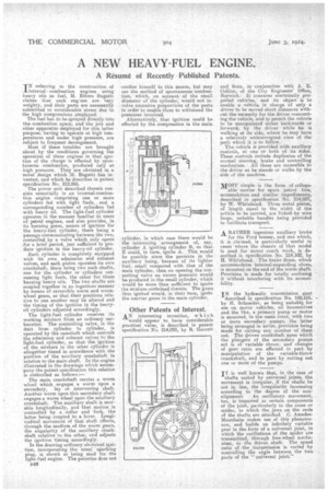
TN referring to the construction of J-internal combustion engines using heavy oils as fuel, M. Ettore Bugatti claims that such engines are very weighty, and their parts are necessarily submitted to considerable 'stress due to the high compressions employed. The fuel has to he sprayed directly into the combustion space, and the jets and other apparatus eniployed for this latter purpose, having to operate at high temperatures and under high pressure, are subject to frequent derangement. Most of these troubles are brought about by the conditions governing the operation of these engines in that ignition of the charge is effected by spontaneous combustion, produced only at high pressure. They are obviated in a novel design which M. Bugatti has invented, and which he describes in patent specification No. 212,866.
The power unit described therein consists essentially in an internal-combustion engine comprising one or more cylinders fed with light. fuels, , and a corresponding numberof cylinders fed with heavy oil. The light-fuel cylinder operates in the manner familiar' to users of petrol engines, and also provides, in its burning gases, means of ignition for the heavy-fuel cylinder, there being a passage communicating between the two, controlled by a valve which, only opens . for a brief period, just sufficient to produce ignition ID the heavy-oil cylinder.
Each cylinder is completely equipped with its own admission and exhaust valves, and each piston operates its own crankshaft, there being two such shafts, one for the cylinder or cylinders consuming light fuels, the other for those burning heavy oils. The two shafts are coupled together in an ingenious manner by means of reversible worm and worthwheel gears, so that their positions relative to one another may be altered and the timing of the ignition in the heavyoil cylinders adjusted accordingly.
The light-fuel cylinder receives its working mixture from an ordinary carburetter. The controlling valve, in the duct from cylinder to cylinder, is operated by the camshaft which controls the admission and exhaust valves to the light-fuel cylinder, so that the ignition of, the mixture in the other cylinder is altogether timed in accordance with the position of the auxiliary crankshaft. in relation to the main shaft. In the engine illustrated in the drawings which accompany the patent specification this relation is controlled as follows:— The main crankshaft carries a worm wheel which engages a worm upon a secondary, lay or intervening shaft.. Another worm upon this secondary shaft engages a worm wheel upon the auxiliary crankshaft. The auxiliary shaft is movable longitudinally, and that motion is controlled by a collar and fork, the latter being coupled to a lever. Longitudinal movement of that shaft affects, through the medium of the worm gears, the angularity of the auxiliary crankshaft relative to the other, and adjusts the ignition timing accordingly.
In the drawing ordinary electrical ignition, incorporating the usual sparking plug, is shown as being used for the light-fuel engine. The patentee does not B46 confine himself to this means, but may use the method of spontaneous combustion, which, on account of the small diameter of the cylinder, would not involve excessive proportions of the parts in order to enable them to withstand the pressures involved.
Alternatively, that ignition could be effected by the compression in the main cylinder, in which ease there would be the interesting arrangement of, say, cylinder A igniting cylinder B, so that B could, in turn, ignite A. This would be possible since the pressure in the auxiliary being, because of its lighter fuel, small compared with that of the main cylinder, then on opening the con. necting valve an excess pressure would be produced in the small cylinder, which would be more than sufficient to ignite the mixture contained therein. ' The gases thus ignited would, in their turn, ignite the heavier gases in the main cylinder.
Other Patents of Interest. AN interesting invention, which
would appear to have considerable practical value, is described in patent specification No. 214,093, by R. Garrett and Sons, in conjunction with A. E. Collins, of the City Engineers' Office, Norwich.. It concerns electrically propelled vehicles, and its object is to enable a vehicle in charge of only a driver to be moved short distances without the necessity for the driver remounting the vehicle, and te permit the vehicle to be manipulated either backwards or forward, by the driver while he is walking at its side, where he may have a relatively uninterrupted view of the path which it is to follow, The vehicle is provided with auxiliary controls, at one or both of its sides. These controls include duplicates of the normal steering, brake and controlling mechaniem. • All these arc accessible to the driver as he stands or walks by the side of the machine.
MOST simple is the form of collaps able carrier for spare petrol tins, accumulators and similar impedimenta, described in specification No. 214,037, by W. Whitehead. . Three metal plates, of length equal to the width of the article to be carried, are linked by wire loops, suitable handles being piovided to facilitate transport.
A RATHER ingenious auxiliary brake
for the Ford tonner, and one which, it ;s claimed, is particularly useful in cases where the chassis of that model is used for motor coach work, is described in specificartion No. 214,102, by H. Whitehead. The brake drum, which accommodates internal-expanding shoes, is Mounted on the end of the worm shaft. Provision is made for totally enclosing it without interfering with its accessi IN the hydraulic transmission gear described in specification No. 190,155, • by H. Schneider, as being suitable for use on motor vehicles, oil locomotives and the like, a primary pump or motor is mounted, in the same rotor, with two or more secondary pumps, the latter being arranged in series, provision being made for cutting any number of them out. The driven crankshaft upon which the plungers of the secondary pumps act is of variable throw, and changes of gear ratio are effected in part by manipulation of the variable-throw crankshaft, and in part by cutting out one or more of the pumps.
IT is well known that, in the case of
shafts united by universal joints, the, movement is irregular, if the shafts be not in line, the irregularity increasing according to the degree of the non
alignment. An oscillatory movement, too, is imparted to certain components of the joint, particularly to the cross or spider, to which the, jaws on the ends of the shafts are attached. C. AmedeeMannheim makes use of this phenomenon, and builds an infinitely variable gear in the form of a universal joint, in which the oscillations of the spider are transmitted, through free-wheel mechanism, to the driven shaft. The speed ratio of thetransmission is varied by controlling the angle between the two parts of the " universal joint."