 1
1 2
2 3
3 4
4 5
5 6
6 7
7 8
8 9
9 10
10 11
11 12
12 13
13 14
14 15
15 16
16 17
17 18
18 19
19 20
20 21
21 22
22 23
23 24
24 25
25 26
26 27
27 28
28 29
29 30
30 31
31 32
32 33
33 34
34 35
35 36
36 37
37 38
38 39
39 40
40 41
41 42
42 43
43 44
44 45
45 46
46 47
47 48
48 49
49 50
50 51
51 52
52 53
53 54
54 55
55 56
56 57
57 58
58 59
59 60
60 61
61 62
62 63
63 64
64 65
65 66
66 67
67 68
68 69
69 70
70 71
71 72
72 73
73 74
74 75
75 76
76 77
77 78
78 79
79 80
80 81
81 82
82 83
83 84
84 85
85 86
86 87
87 88
88 89
89 90
90 91
91 92
92 93
93 94
94 95
95 96
96 97
97 98
98 99
99 100
100 101
101 102
102 103
103 104
104 105
105 106
106 107
107 108
108 109
109 110
110 111
111 112
112 113
113 114
114 115
115 116
116 117
117 118
118 119
119 120
120 121
121 122
122 123
123 124
124 125
125 126
126 127
127 128
128 129
129 130
130 131
131 132
132 133
133 134
134 135
135 136
136 137
137 138
138 139
139 140
140 141
141 142
142 143
143 144
144 145
145 146
146 147
147 148
148 149
149 150
150 151
151 152
152 153
153 154
154 155
155 156
156 injection Pump of Ingenious Design
Page 112
If you've noticed an error in this article please click here to report it so we can fix it.
AN injection pump for use with small oil engines forms the subject of patent No. 692,068, from W. Staege,
22 Auerstrasse, Karlsruhe Durlach, Germany. The pump described is designed to deliver charges of as little as 2 Cu. mm. at a speed of 5,000 r.p.m.
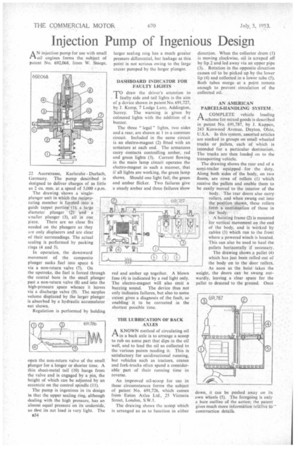
The drawing shows a singleplunger unit in which the reciprocating member is formed into a guide tappet portion (1), a large diameter plunger ()• and a smaller plunger (3), all in one piece. There are no close fits needed on the plungers as they are only displacers and are clear of their surroundings. The actual sealing is performed by packing rings (4 and 5).
In operation, the downward movement of the composite plunger sucks fuel into space 6 via a non-return valve (7). On the upstroke, the fuel is forced through the central bore in the small plunger past a non-return valve (8) and into the high-pressure space whence it leaves via a discharge valve (9). The surplus volume displaced by the larger plunger is absorbed by a hydraulic accumulator not shown.
Regulation is performed by holding
open the non-return valve of the small plunger for a longer or shorter time. A thin sheet-metal tail (10) hangs from the valve and is engaged by a pin, the height of which can be adjusted by an eccentric on the control spindle (11).
The pump is ingenious in its design in that the upper sealing ring, although dealing with the high pressure, has an almost equal pressure on its underside, so thqt its net load is very light. The a54 larger sealing ring has a much greater pressure differential, but leakage at this point is not serious owing to the large excess pumped by the larger plunger.
DASHBOARD INDICATOR FOR FAULTY LIGHTS
T?draw the driver's attention to aulty side and tail lights is the aim of device shown in patent No. 691,727, by J, Kemp, 7 Lodge Lane, Addington, Surrey. The warning is given by coloured lights with the addition of a buzzer.
The three " legal " lights, two sides and a rear, are shown at 1 in a common circuit. Included in the same circuit is an electro-magnet (2) fitted with an armature at each end. The armatures carry contacts controlling amber, red and green lights (3). Current flowing in the main Tamp circuit operates the electro-magnet in such a manner, that if all lights are working, the green lamp shows. Should one light fail, the green and amber flicker. Two failures give a steady amber and three failures show red and amber up together. A blown fuse (4) is indicated by a red light only. The electro-magnet will also emit a buzzing sound. The device thus not only indicates failures, but also to some extent gives a diagnosis of the fault, so enabling it to be corrected in the shortest possible time.
THE LUBRICATION OF BACK AXLES
AKNOWN method of circulating oil in a back axle is to arrange a scoop to rub on some part that dips in the oil well, and to lead the oil so collected to the various points needing it. This is satisfactory for unidirectional running, but vehicles such as tractors, cranes and fork-trucks often spend a considerable part of their running time in reverse.
An improved oil-scoop for use in these circumstances forms tho subject of patent No. 691,726, which comes from Eaton Axles Ltd., 25 Victoria Street, London, S.W.I.
The drawing shows the scoop which is arranged so as to function in either direction. When the collector drum (I) is moving clockwise, oil is scraped off by lip.2 and led away via an upper pipe (3). Rotation in the opposite direction causes oil to be picked up by the lower lip (4) and collected in a lower tube (5). Both tubes merge at a point remote enough to prevent circulation of the collected oil.
AN AMERICAN PARCELS-HANDLING SYSTEM,
ACOMPLETE vehicle loading scheme for mixed goods is described in patent No. 691,787, by J. Kappen, 243 Kenwood Avenue, Dayton, Ohio, U.S.A. In this system, assorted articles are stacked in groups on small wheeled trucks or pallets, each of which is intended for a particular destination. The trucks are then loaded on to the transporting vehicle.
The drawing shows the rear end of a semi-trailer equipped for the duty. Along both sides of the body, on two floors, are rows of rollers (I) which receive the pallets and enable them to be easily moved to the interior of the body. The rear doors also carry rollers, and when swung out into the position shown, these rollers form a continuation of those in the body.
A hoisting frame (2) is mounted for vertical movement on the end of the body, and is worked by cables (3) which run to the front where a powered winch is located. This can also be used to haul the pallets horizontally if necessary. The drawing shows a pallet (4) which has just been rolled out of the body on to the door rollers. As soon as the hoist takes the weight, the doors can be swung outwardly, leaving a clear space for the pallet to descend to the ground. Once
down, it can be pushed away on its own wheels (5). The foregoing is only a bare outline of the action; the patent gives much more information relative Oa construction detail's.