


An Improved Submerged
Page 54
If you've noticed an error in this article please click here to report it so we can fix it.
jet Carburetter
A Re'sume` of Patent Specifications that Have Recently Been Published
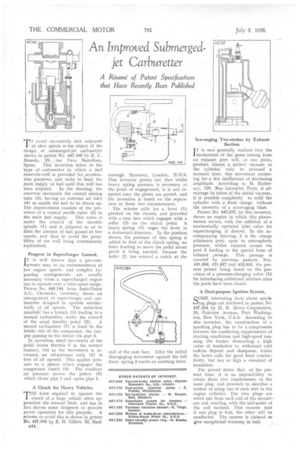
rro avoid excessively rich mixtures 1'atlow speeds is the object Of the design , of s. submerged-jet carburetter shown in patent No.. 447,160 by E. C. Buxeda, , 18, .; rue. Vico; Barcelona,
Spain. This invention refers to the type ofcarburetter in Which a fuel reservOir-well is provided fors acceleration purposes, and seeks to limit the main supply of fuel until this well has been emptied. In the drawing,' the reservoir surrounds the central mixing tube (3), having an external air inlet (4) to enable the fuel to be drawn up. The improvement consists of the provision of a conical needle valve (2) in the •main fuel supply. This valve is under the control of the throttle spindle (1) and is adjusted so alto limit the amount of fuel passed at low speeds, and thus to avoid the possibility of the well being continuously replenished.
Progress in Supercharger Control.
IT is well known that a pre-comlpressor may be an embarrassment at low engine speeds, and complex bypassing arrangements are usually necessary when a supercharged engine has to operate over a wide speed range. Patent No. 446,144, from Auto-Union A.G., Chemnitz, Germany, shows an arrangement of supercharger and carburetter designed to operate satisfac torily at all speeds. The induction manifold has a branch (1) leading to a normal carburetter, under the control of the usual throttle pedal (2). A second carburetter (7) is fixed to the intake side of the compressor, the output passing to the intake via pipe 5.
In operation, small movement of the pedal works throttle .8 in the normal manner, but as the movement is increased, an oil-pressure cock (3) is first of all opened. This applies pressure to a piston which engages the compressor clutch (4). The resultant air pressure moves the piston (6) which closes pipe I and opens pipe 5.
A Clutch for Heavy Vehicles.
THE force required to operate the clutch of a large vehicle often approaches the manual limit, and has in fact driven some designers to provide power operation for this purpose. A scheme to avoid this is shown in patent No. 447,084 by E. H. Gillett, 32, Marl
1344
borough Mansions, London, N.W.6. This inventor points out that whilst heavy spring pressure is necessary at the point of enOgement, it is not required once the plates are parted, and his invention is based on the separation of these two circumstances.
• The scheme calls for a lever (1) pivoted on the chassis, and provided with a cam face which engages• with a roller (2) on the clutch pedal. A heavy spring (3) urges the lever in a downward direction. In the position shown, the pressure of this spring is added to that of the clutch spring, no force tending to move the pedal about pivot 4 being exerted, because the roller (2) has entered a notch at the Scavenging Two-strokes by Exhaust Suction.
iT is now generally realized that the momentum of the gases issuing from an exhaust port Will, at one point,' produce almost a perfect vacuum in the cylinder; only to rebound a moment later, this movement persisting for a: few oscillations of decreasing amplitude. ACcotding to M. Kadenacy, 120; Rue .Lecourbe, Paris, if advantage be taken of the initial vacuum, it is possible completely to refill the cylinder with a fresh charge, without the necessity of a scavenging blast.
Patent No, 447,537, by this inventor, shows an engine in which this phenomenon occurs, with the addition of a mechanically operated inlet valve for supercharging, if desired. In the accompanying drawing, 3 is the charge admission port, open to atmospheric pressure, whilst exhauat occurs via port 2 leading to the special form of exhaust . passage. This passage is covered by previous. patents, Nos. 931,856, 931,857 and 433,502, the present patent being based on the provision of a pressure-charging valve (1)' for introducing additional mixture after the ports have been closed.
A Dual.purpo.se Ignition System.
SOME interesting facts. about sparlsing plugs are disclosed in patent No. 447,484 by H. B. Motor Corporation, 18, Fairview Avenue, Port Washington, New York, U.S.A. According to this inventor, the construction of a sparking plug has to be a compromise between the conflicting requirements of starting conditions and high-speed running, the former demanding a high _ value of insulation to withstand cold casbon deposit and dampness, whilst the latter calls for good head conductivity, but not so high a standard of insulation.
The patent states that, at the present time, it is an impossibility to attain those two requirements in the same plug, and proceeds to describe a system of using one of each sort in the engine cylinder. The two plugs are wired one from each end of the secondary coil winding, with the mid-point of the coil earthed. This ensures that if one plug is foul, the other will be unaffected. The system is claimed to give exceptional economy in fuel.