


A Vehicle for Both
Page 54
Page 55
If you've noticed an error in this article please click here to report it so we can fix it.
ROAD and RAIL
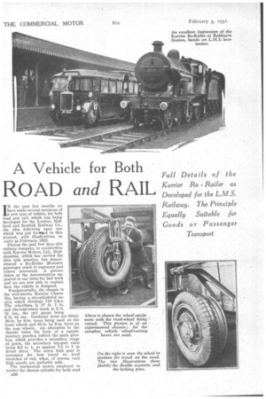
Full Details of the Karrier Ro Railer as Developed for the L.M.S. Railway. The Principle Equally Suitable for Goods or Passenger Transport
IN the past few months we have made several mentions of a new type of vehicle, for both road and rail, which was being developed for the London, Midland and Scottish Railway Co., the idea following upon one which was put forward in this journal, with illustrations, as early as February, 1925.
During the past few days this railway company, in conjunction with Karrier Motors, Ltd., Huddersfield, which has carried the idea into practice, has demonstrated a Ito-Railer 26-seater passenger coach to engineers and others interested. A picture taken at the demonstration appeared in our issue for last week and we are now able to explain how the vehicle is designed.
Fundamentally, the chassis is the well-known Karrier Chaser Six, having a six-cylindered engine which develops 110 b.h.p. The wheelbase is 17 ft. 1 in. and the road-wheel track is (I ft. 31 ins., the rail gauge being 4 ft. 81 ins; Goodyear tyres are fitted, 36-in. by 6-in. tyres being used on the front wheels and 42-in. by 9-in. tyres on the rear wheels. An alteration to the chassis takes the form of a supplementary gearbox behind the main gearbox, which provides a secondary range of gears, the secondary top-gear ratio being 4.2 to 1, as against 7.2 to 1 in direct drive. The extra high gear is necessary for fast travel on level . stretches of rail, when, of course, very high speeds are perfectly safe.
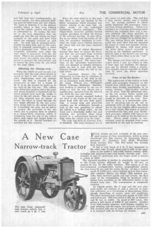
The mechanical means employed to render the chassis suitable for both road B36 and rail dety`are fundamentally, extremely simple, the same principle holding good for both front and rear wheels. We want to describe it in the plainest possible terms., so that, even without seeing the vehicle, readers will not fail to understand it. To explain the matter in the most elementary way, one might say that the rail wheels are fixed normally 'to the axles and have hubs which are extended outward on each side. On each hub is mounted eccentrically an outer hub, and on this °titer hub is mounted eccentrically a wheel with a pneumatic tyre. When the two eccentrics neutralize each other the road wheel is concentric with the rail wheel. This is the position adopted for road travel, two strong pins being employed to preserve the concentricity and to convey the drive from the rail wheel to the road wheel.
Effecting the Change-over.
Where the vehicle is used on rail, it is necessary that the road wheel should be raised so that it will clear points and other obstructions near the railway track. All that is required for the change-over is that, for a length of 40 ft. or so, the ground be made up to the level of the rail top. The vehicle then drives into position above the track and moves forward or backward off the raised ground level until the weight is taken by the rail wheels. The two pine are thee removed and, by means a levers, the wheel is raised through the two stages afforded by the two eccentrics, being held in the raised position by re-inserting the pins, not as before to connect the eccentrics to the rail wheel, but to position them in relation to a slipper-block structure, which is withdrawn from the side of the vehicle above each wheel and hinged down on the outside of it. Special brackets are provided for this purpose.
When the road wheel is in this position there is only one bearing in the whole mechanism which possesses any relative velocity to the main huh. In other words, all the road-wheel mechanism remains stationary. The slipper-block structure permits limited vertical movement to Anew, for flexing of the ordinary springs. It also offers, due to its radius from the centre of the axle, the necessary resistance to overcome the slight static friction between the wheel hub and the inner eccentric bearing The pins are of robust dimensions because they have to convey the drive, and they are prevented from working out, as a result of vibration, by a simple automatic lock, easily overcome by a jerk of the hand. The wheel bearings, of the adjustable tapered-roller • type, are disposed at seitable distances inside the hub to deal with the load imposed through either the rail or the road wheel.
An important feature for the elimination of noise due to vibration of the flanged wheels on the rails is .the use of laminated wood wheels made by the Lang Wheels Co., Hillingdon Reath, Uxbridge, Middlesex. Satisfactory braking is obtained by the use of drums on only the rear wheels and a sanding gear, operated from the driver's cab, feeds the rear rail wheels.
As regards details, standard buffers are fixed to the frame at' the rear and stand flush with the rear body panelling. A towing hook and screw-link coupling can be -withdrawn through a trap in the rear panelling to attach the vehicle to a railway train. At the front end a detachable buffer bar and coupling are provided, these being housed in a compartment beneath the body when the vehicle is on the road.
The body was built by Cravens, Ltd., of Sheffield. The main entrances are in the centre on each side. The roof has deep lateral camber and is arched over the central vestibule to afford
• ample headroom flit. passengers entering ftom etation platforms. When it is necessary to cover-the intervening space between the vestibule floor• and a station platform the stesis provided on each Side for entering the vehicle from the road are bridged by a sliding floor. The two sliding floors are housed beneath the main floor and are .operated by means of racks and sprocket wheels, actuated by chains with hand grips, the latter being housed vertically in alcoves in the vestibule partitions. A tell-tale light in the driver's cab informs him when either floor is in the " out" position.
The change-over from road to rail occupies about I min, per wheel, so that if -four men are available the Changeover can be effected within a minute. Five minutes may be regarded as ample time to cover, the whole operation in volved.
Uses of the Ro-Railer.
• The application of the vehicle to both goods and passenger transport on the branch lines -which, due to road competition, have become unprofitable, is, of course, obvious. Door-to-door service can be given, with the advantage that, on the rail section. higher speeds can be attained, in complete safety, than would be desirable on the road. Incidentally, there is a considerable economy in operating cost on the rail as compared with on the road, this being due to the low tractive effort necessary for a rail vehicle. The centre of gravity is ssatisfactorily low, and even doubledeck passenger vehicles with four or six wheels can be built on the Re-Rail principle. Heavy goods trucks, so constructed, could be detached from trains and hauled on the road by tractors.