


ANOTHER HYDRAULIC TRANSMISSION.
Page 30
If you've noticed an error in this article please click here to report it so we can fix it.
A Résumé of Recently published Patents.
There is undoubtedly something fascinating in the idea of an infinitely graded change-speed gear on the hydraulic principle, and we therefore welcome the present activity in regard to this form of transinission which is apparent in the current patent specifications. Three weeks ago we had the pleasure of discussing, in these columns, one application of the hydraulic principle, the
patentee being Dr. Eele.-Shaw. This week, Mr. H. E. Peacock enters the &Imo field with another of equal interest. it is described in patent specification No. 136,681.
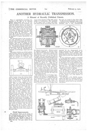
The principal object of the inventor in this case, according to the specification, has been that of arranging the whole apparatus, both pump and motor, in such compass that it can conVeiniently be placed within the wheel of a mot:or Vehicle. The amount of liquid which will be permanently carried by the gear appears to be small, but the specification is, wittingly or unwittingly, vague upon the The pump cylinders are drilled radially from two discs ; those of the motor from a, single disc which, in the machine,iS sandwiched in between the other two. All three are located on a central shaft,
which, besides being the driving shaft also does duty as a distributor valve be tween the cylinders of the pump and those of the motor. Outside the two pump discs ie a like number of eccentrics. • They are set at 180 degrees one to another, and are driven by the driving shaft, the same one which also has al
ready been mentioned. Provision is made for adjustment of the eccentricity of the eccentrics. Rocking levers, one to each pair of pump cylinders, bear at their ends on the eccentrics, and are pivoted in the centre disc. The reciprocating movement imposed on the rocking levers . by the eccentrics is transmitted to the pistons of the pumps. The liquid from the pumps is transferred to the motor cylinders through the drivingshaft eum distributor-valve; the plungers of the latter cylinders bear on an internal cam which is integral with the rim of the hub of the driven wheel. Such is the principle of the working of this device. Variation of the throw of the eccentric alters the stroke of the pump and the gear ratio.
Detail Improvements:
The principal object of the design of the side-tipping gear which is described by the Eagle Engineering Co., Ltd., in specification No. 136,763, is that of reducing the effort which is necessary to effect the tip. The gear allows of the
C44 wagon being tipped to either aide, and is simple in construction. The underside of the wagon body is fitted with elan' nels which are set transversely, and with
the channel downwards. 'Rollers Carried ,brackets dispdsed at intervals aremg the sides of the -imdeeframe. engar,e.with the. channels. . TWO transversc screwed: shafts are: provided, one at each end 'of the body; they are operated by means of• I single lengitudinal shaft through. bevel gears. The main shaft_iS driven by hand, using the usual formof handle which fits on to either end of the shaft, whichis squared to receive it. • Nuts on the screwed spindles are coupled .by'linke to the bodywork of the wagon. Preliminary movement of the nuts causes the body to move sideways on the rollers, until a central stop-comes into contact with the rollers on the side towards which tipping is intended4Afterwards further movement of the nuts lifts the body and accomplishes: thee tip. The carburetter by C. H. Pugh, Ltd., which is the subject of specification No. 136,676, is of the type in which theepetrol jet is surrounded by a small air j6t, the effect of the •combination being the thorough atomization of the fuel as it leaves the former, before it mingles with
the main air supply in the choice tube, In the friction transmission gear which is patented in No. 1Z6,640 by Palladium Ant:wars, Ltd., a cam, automaticalljr operated by the change-speed lever, brings progressively into operation an :auxiliary -spring which provides adcliVenal pres.sure between the driving and driven discs as the lower gears are utilized.
In the construction which is described in specification No. 136,611 by• iJ. Bamford, the front axle of a tractor s pivoted on the front, either of the engine case, if the machine is one of the frameless type, or, if a frame is available, on a pm in the front of it. The connection between axle and frame may either be direct or through the medium of springs.
The engine starter which is patented by J. W. Phillips, in No. 136,744, provides for the direct inhalation, by the engine when slowly turned over by hand or other means, of a rich mixture of petrol •and
W.-Idnallin, in No. 136,751, mounts, within the shaft of a starting handle, a lock of the Yale type, by which he locks the handle against use by any unauther ized person.