


Ford has designs on its future programs
Page 48
Page 49
Page 50
If you've noticed an error in this article please click here to report it so we can fix it.
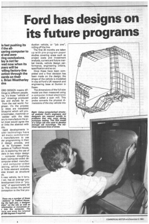
is fast pushing its if the all uering computer to al and awe ring conclusions. lay is not far Ived now when its iners will be 'oiling factory-line uction through the oards on their s. Brian Weatherley sins ORD DESIGN means dif:hings to different people. -ne, it's those "vehicle of ure" drawings produced ists and stylists far refrom the real world. For gineer, it's the process )y ideas are translated blueprint which will proe toolmaker, machinist or welder with the data ary to manufacture the ar;Lit most would agree the er links the abstract with
rapid developments in uter technology have ed many commercial 3 manufacturers to use lter programming in their design process, and at its European truck uarters at Trafford House, on, is exploring the use of iters in two major design — computer draughting, icam (computer-aided de:omputer-aided manufac; and computer-aided leering, which includes ar finite element analysis, vise known as structural h new vehicle, be it lorry, r car, has an average prolevelopment time or "pro:ycle" of approximately 60 is. This covers the period conception to the first pro duction vehicle, or "job one", rolling off the line.
The first 30 months are taken up with pre-program paper studies covering areas such as project costs and investment analysis, current and future market trends, vehicle -design performance, engineering criteria, specification and so on.
Once these have been completed and a final decision has been made on the design, the shape of the vehicle is modelled in clay at Ford's UK research and engineering base at Dunton in Essex.
The dimensions of the full-size model are then measured using a computer-linked electronic probe called a scan mill. This probe converts the physical dimensions of the clay vehicle into
digital form and feeds it into the Trafford House computer draughting system, which finally represents the model as a line diagram that can be displayed on a visual display unit.
This whole process shows up all the unseen imperfections in the clay model, and if necessary the draughting computer carries out a process known as "smoothing", which involves feeding amended dimensions back to the scan mill. This then physically trims excess material from the clay model until the final specification is reached.
When the final dimensions of the vehicle exterior are established, which normally takes a few days, they are stored in the computer network.
As the Scan Mill determines only the outside shape of the vehicle, at the same time as the model is being approved, the designers decide on the internal structure and layout, and in particular where and how each component or sub-structure will be produced and supplied.
The design department at Trafford House then sends the approved component designs to the suppliers, which for engine, gearbox and axles come from within Ford.
Two methods of transmitting this information are currently used. The first is the timehonoured method of physically drawing a "hard" copy of a component design in the form of an approved blueprint and sending it to the supplier.
The other, and one which Ford is quickly expanding, is to reproduce it electronically as a line drawing from data collated by the scan mill or stored in the computer. This is done by using a computer programming system marketed and developed by Ford called product design graphic system or PDGS.
Developed in the United States on car design, PDGS is basically an electronic drawing board capable of producing highly sophisticated engineering drawings, while eliminating many of the repetitive and laborious stages in the drawing of complex irregular shapes.
The designer uses a large video screen linked to a minicomputer in which highly complex programs are stored. Using data either held on computer or by using a light pen to communicate with the computer directly via the video screen, the designer can create and refine designs in three dimensions, manipulating all points, lines or surfaces by just pointing at the screen with the light pen.
Parts displayed on the vdu can even be rotated through 360 degrees to produce a more convenient view.
This animated display is particularly useful in the case of moving components such as steering mechanisms, which can be checked against bodywork to ensure there is no fouling.
PDGS is currently used by Ford in Europe, America and Australia. The company's designers can transfer design ideas by telephone or -satellite from
any one of its 440 PDGS screens to another halfway round the world.
In addition, component manufacturers capable of receiving PDGS can rapidly obtain parts information for manufacture directly from any Ford designer.
This virtually instantaneous trnsmission of computer-aided design data reduces production lead time and costs enormously, and enables suppliers to change component specifications whenever it is required.
PDGS can also generate numerical data for the control of tool and die-making machines in manufacturing, thus eliminating the complex drawings and templates normally required, as well as improving the quality and accuracy of the tools themselves.
It is not difficult to envisage a direct dialogue system like PDGS removing every stage between design and manufacturing (human or otherwise), with designers linked to factory-floor, numerically controlled (NC) machines producing computerdesigned components or structures in a matter of minutes.
The system, however, is still very much in its infancy with many component manufacturers, even within Ford, not connected to the PDGS network. For this reason, both old and new methods run in parallel at Basildon.
Before any vehicle enters production, every part of it will have been fully tested. To ensure each component can stay the course, be it engine, gearbox or wheelnut, it will have been subjected to stringent structural analysis in the design stage.
Traditionally, this has been done by experienced design en gineers and structural anal„ calculating imposed stress I tors and designing the prod to fit. Theories were then pro) right or wrong on protot■ vehicles.
Over the last decac however, a number of car E. commercial vehicle manufact ers have begun using comput for structural or finite elem analysis as a means of rn. effectively understandi structures and of weeding design non-starters.
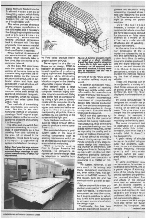
At the same time as the ex nor dimensions of the c model are collected by the se mill and converted by the co puter into line drawin€ programs are also produced V take the digital drawings of t truck or van and convert thi into three-dimension structures, which are th divided into matrices represe ing the lines of stress in t vehicle.
These 3-D drawings can th be subjected to a variety of plied forces across any numt of points on the matrix by t computer, and the resul displayed in animated form or vdu.
By using computerised FE designers can actually see p posed structures or componer flexing or deforming und loads. This gives them a grE insight into the component a its design. For example, t effect of road shock on a c mounting can be clearly seen.
The same component test to destruction on a prototy vehicle yields little initial formation, other than that it h actually failed. It doesn't t the designer why.
A great variety of simulat forces can be applied using co outer FEA programs, such linear forces and displaceme variable frequency vibratioi gravity and temperatu changes (which are used great effect in engine block c sign).
By using a computer, resu can be obtained far quicker th traditional calculations, and w a greater degree of accuracy. spite of the initially long peni of time needed to programme the required simulated fore and effects on the comput once they are assembled, th can be recalled instantly a used repeatedly, allowing c signers and engineers to resol speedily any design relat problems before they reach t full manufacturing stage.
As a part of the FEA progra Ford also carries out dynar analysis by computer, wh
vers the effects of noise and )rations on vehicle suspension stems and body panels.
Fourteen minicomputers are ed on commercial vehicle dcam work at Trafford House, d FEA is done by a large mainme computer at the Ford arid Headquarters in Dearborn ar Detroit which is linked to afford House by a trans-Atlantelephone line. All incoming d outgoing data is assembled the building by a single nicomputer and all programs d results are stored on magtic discs ready for use at any e.
f required, Ford's designers d engineers at Trafford House n link up with further compu • facilities at the nearby rearch and engineering complex Dunton, and its West German unterpart at Merkenich near logne.
4Ithough it's still early days at rd, a number of computer FEA Dduct models have been proiced, among them a full uctural model of Ford's new ht van range and dynamic alysis structural models of the rrent Transit, which have been ed in vibration testing to demine a finite life for van ells.
411 the data gained from the FEA model of the existing Transit, will be used in the development of its replacement. FEA and dynamic analysis models of new engine blocks have also been produced.
During the development of the Ford Cargo range, computer FEA was used to discover why a number of prototype cab mountings failed during rough road testing. By simulating the conditions on the structural model, appropriate strengthening was developed, and a number of Cargo FEA cab models are now
stored on disc ready for use in any further product refinement.
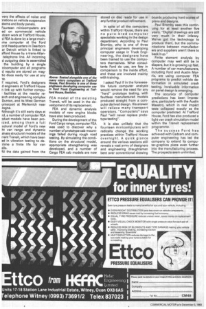
In spite of all the computers within Trafford House, there are no pure-bred computer specialists working in the design department. According to Paul Bromby, who is one of three principal engineers developing computer usage in Truck Engineering, the designers have been trained to use the computers themselves. What consultants Ford do use, are few in comparison to the inside effort, and these are involved mainly with training.
I asked Paul if in the foreseeable future computer analysis would remove the need for any "hard" prototype testing, with faultless manufactured models produced straight from a computer derived design. His answer will relieve many transport operators. "Computers" says Paul "will never replace prototype testing".
It is also unlikely that the fourteen minicomputers will radically change the working practices within Trafford House overnight. A quick glance around the various sections still reveals a vast army of designers and engineering draughtsmen bent over conventional drawing boards producing hard copies of plans and designs.
Paul Bromby sees this continuing for at least another five years. "Digital drawings are still very much in their infancy. We've got the technology to produce them., but the communications between manufacturers and suppliers aren't there to back it up."
Finite element analysis by computer may well still be in diapers, but it is growing up fast. A number of car manufacturers, including Ford and Austin Morris, are using computer FEA programs to predict vehicle deformation in simulated crash testing. Invaluable information on panel design is emerging.
The accuracy of computer predictions has been impressive, particularly with the Austin Maestro, which in real impact tests collapsed exactly as the computer predicted. At Trafford House, Ford has also produced a light van crash simulation model within the Transit replacement programme.
The success Ford has achieved with Cadcam and computer engineering has led the company to extend its computer-graphics plans even further into the manufacturing process. The prospects seem unlimited.