


A Device . for Storing Energy
Page 80
If you've noticed an error in this article please click here to report it so we can fix it.
DUSES and other vehicles that spend
a large proportion of, their time in stopping and starting are continuously expending much energy in accelerating and then almost immediately dissipate it in braking. A scheme for providing an energy-storing device for use in these circumstances is shown in patent
No, 715,602, by Daimler-Benz A.G., Stuttgart-Untertiirkheim, Germany.
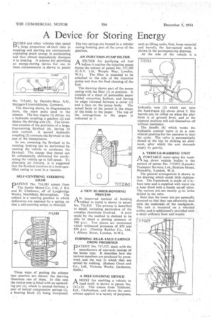
The drawing shows, in diagrammatic form, the main parts used in the scheme. The bus engine (1) drives, via a hydraulic coupling, a gearbox (2) and thence the driving axle (3). The invention consists of the provision of a large, free-running flywheel (4), having its axis vertical. A second hydraulic coupling (5) connects the flywheel to the rest of the transmission.
In use, assuming the flywheel to be running, braking can be performed by causing the vehicle to accelerate the flywheel. The energy thus stored can be subsequently abstracted for accelerating the vehicle up to full speed. To eliminate air friction, it is suggested that the flywheel revolves in a hydrogenfilled casing or even in a vacuum.
SELF-CENTRING STEERING GEAR
PATENT No. 716,283 comes from 1 The Austin Motor Co., Ltd., J. Rix and H. Challenor, all of Longbridge Works, Northfield, Birmingham. The subject is a steering gearbox in which deflections are opposed by a spring, so that a self-centring action is obtained.
Three ways of putting the scheme into practice are shown; the drawing illustrates one of them. In this case the rocker arm is fitted with an upstanding pin (1), which is centred between a pair of helical compression springs (2), a bearing block (3) being interposed.
The two springs are housed in a tubular casing forming part of the cover of the gearbox.
AN INJECTION-PUMP FILTER A FILTER for purifying oil fuel 1-1. before it reaches the injection pump forms the subject of patent No. 717,280 (C.A.V. Ltd., Warple Way, London,
W.3.). The filter is intended to be attached to the side of the injection pump and does the final cleaning of the fuel.
The drawing shows part of the pump casing with the filter (1) in position. It consists of a sheet of permeable paper folded concertina fashion, and having its edges clamped between a cover (2) and a face on the pump body. The actual basis of the patent is the shape of the folds in the paper. The top of the corrugations in the paper is indicated at 3.
ANimproved method of bonding rubber to metal is shown in patent No. 716,810. The process is described in detail, including particulars of the complex chemicals involved. A joint made by the method is claimed to be able to stand a parting pressure of 700 p.s.i. Test pieces are mentioned which withstood pressures of 870 and 890 psi. (Dunlop Rubber Co., Ltd., 1 Albany Street, London, N.W.1.
FORMING REAR-AXLE CASINGS FROM PRESSINGS
PATENT No. 717,527, deals with the manufacture of rear-axle casings of the banjo type. It describes how the various members are produced by presswork and the way in xvhieh they are united by welding. (Rubery Owen and Co., Ltd., Victoria Works, Darlaston, Staffs.)
A SELF-LOADING DEVICE
A HOIST for enabling a vehicle to ra• load itself, is shown in patent No. 717,133. This comes from Telehoist, Ltd., Cheltenham, and shows the same scheme applied to a variety of purposes, such as lifting sacks, bins, loose material and barrels; the last-named outfit is shown in the accompanying drawing. At the side of the vehicle is a
hydraulic rain (1) which can raise the load-frame (2) about pivot 3. The barrels can be rolled on when the platform is at ground level, and at the topmost position will roll themselves off without assistance.
The handle (4) which works the hydraulic control valve is in a convenient position for the operator to start the cycle. The valve is automatically closed at the top by striking an abutment, after which the arm descends empty by gravity.
A VEHICLE-WASHING UNIT PA.
A PORTABLE water-spray for was down vehicle bodies is the
subject of patent No. 717,025 (Laundry Transport Services, Ltd., Stratton House, Piccadilly, London, W.1).
The general arrangement is shown in the drawing which needs little explanation. The framework is made of bore tube and is supplied with water via a hose fitted with a handy on-off valve.
The various jets are merely holes drilled in the tube.
Note that the lower jets are upwardly directed so that they can effectively deal with the underside of the mudguards. The unit is mounted on a wheeled trolley and. is additionally provided with a short ordinary hose and nozzle.