


A New Transmission System for Tractors
Page 60
If you've noticed an error in this article please click here to report it so we can fix it.
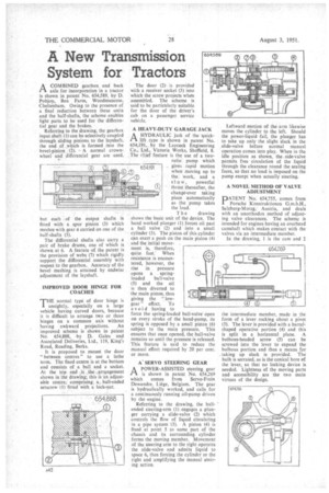
ACOMBINED gearbox and back axle for incorporation in a tractor is shown in patent No, 654,589, by D. Pobjoy, Box Farm, Woodmaneote, Cheltenham. Owing to the presence of a final reduction between these units and the half-shafts, the scheme enables light parts to be used for the differential gear and the brakes.
Referring to the drawing, the gearbox input shaft (1) can be selectively coupled through sliding pinions to the layshaft, the end of .which is formed into the bevel-pinion (2). A normal crownwheel and differential gear are used.
but each . of the output shafts is fitted with a. spur pinion (3) which meshes with gear 4 carried on one of the half-shafts (5).
The differential shafts also carry a pair of brake drums, one of which is shown at 6. A feature of the patent is the provision of webs (7) which rigidly support the differential assembly with respect to the gearbox. Accuracy of the bevel meshing. is attained by endwise adjustment of the layshaft.
INIPROVED DOOR HINGE FOR COACHES
THE normal typo of door hinge is unsightly, especially on a large vehicle having curved doors, because it is difficult to arrange two or three hinges on a common axis without having awkward projections. An improved scheme is shown in patent No. 654,888, by D. Gales and Associated Deliveries, Ltd., 119, King's Road, Reading, Berks.
It is proposed to mount the door " between centres" to use a lathe term. The fixed centre is at the bottom and consists of a ball and a socket. At the top.• end is _the.. arrangement shown in the drawing; this is an adjustable centre, comprising,. a . ball-ended setscrew (1) fitted with a lock,nut. The door (2) is provided with a receiver socket (3) into which the screw projects when assembled. The scheme is said to be particularly suitable for the door of the driver's cab on a passenger service vehicle.
A HEAVY-DUTY GARAGE JACK
AKYDRAULIC jack of the quicklift type is shown in patent No. 654,191, by the Laycoek Engineering Co., Ltd., Victoria Works, Sheffield, 8. The chief feature is the use of a two
ratio pump which . gives rapid motion when moving up to the work, and a slaw, powerful thrust thereafter, the change-over taking place automatically as the pump takes the load.
The drawing
shows the basic unit of the device. The hand worked plunger (1) forces oil past a ball valve (2) and into a small cylinder (3). The piston of this cylinder can exert a push on the main piston (4) and the initial movement is, therefore, quite fast: When resistance is encountered, however, the rise in pressure opens a spring
loaded ball-valve (5) and the oil is then diverted to the main piston, thus giving the " low gear " effect. To avoid having to force the spring-loaded ball-valve open on every stroke of the hand-pump, its spring is opposed by a small piston (6) subject to the main pressure. This ensures that once opened, the ball-valve remains so until the pressure is released. This feature is said to reduce the manual effort required by 20 per cent. or more.
A" SERVO STEERING GEAR
A POWER-ASSISTED steering gear
is shown in patent No. 654,269 which comes from Servo-Frein Dewandre, Liege, Belgium. The gear is hydraulically worked, and calls for a continuously running oil-pump driven by the engine.
Referring to the drawing, the ballended steering-arm (1),engages a plunger carrying a slide-valve (2) which controls the how of liquid circulating in a pipe system (3). A piston (4) is fixed at point 5 to same part of the chassis and its surrounding cylinder forms the moving member. Movement of the steering arm to the right operates the slide-valve and admits liquid to space 6, thus forcing the cylinder to the right and amplifying the manual steering action Leftward motion of the-arm likewise moves the cylinder to the left. Should the power-liquid fail, the plunger has to take up only the slight slack in the slide-valve before normal manual operation comes into play. When in the idle position as. shown, the-side-valve permits free circulation of the liquid through the clearance round the sealing faces, so that no load is imposed on the pump except when actually steering.
A NOVEL METHOD OF VALVE ADJUSTMENT
PATENT No. 654,755, comes from Porsche Konstruktionen G.m.b.H., Salzburg-Morzg, Austria, and deals with an unorthodox method of adjusting valve clearances. The scheme is intended for engines having an overhead camshaft which makes contact with the valves via an intermediate member.
In the drawing, 1 is the cam and 2 the intermediate member, made in the form of a lever rocking about a pivot (3). The lever is provided with a barrelshaped operative portion (4) and this is split in a horizontal plane. A hulbons-headed screw (5) can be screwed into the lever to expand the bulbous portion and thus a means for , taking up slack is provided. The bulb is serrated, as is the conical bore of the lever, so that no locking device is needed. Lightness of the moving parts and accessibility are the two main virtues of the design.