


A FRENCH CABLE PLOUGHING SET.
Page 30
If you've noticed an error in this article please click here to report it so we can fix it.
A Résumé of Recently Published Patents.
Tractors and agricultural machinery generally loom large in the patent specifications with which we have to deal this week. The first description on this page is concerned with a light cable ploughing set, very similar in its broad ()alines, as we shall show, to that of MeLarens, which had reference recently, both on this SPatetits) page, and in the general news columns of this journal. The second specification with which we deal, although it is not actually confined in its application to tractor construction, is, nevertheless, meant to be applied to that class of work, as is evidenced by the actual wbrding of the specification, wherein the inventor specifically mentions agricultural tractors.
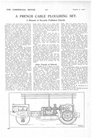
Specification No. 144,861, by Georges Saur, offers an admirable opportunity of comparing French and British methods of attaining the same specific object. Both have in view the design of a machine ler cable ploughing, which, by comparison with those usually employed 'for the same purpose, shall be light, cheap, and simple. In the case of the French machine the whole is described as being supported by a "tractor chassis,' and, judging from the drawing, the inventor would appear to be familiar with locomotive practice, since the frame is constructed on lines strongly reminiscent of those of a railway engine' namely, -cleeip, flat-plate sides, . gusseted, and coupled by other flat plates, the junction between cross members and main frame being by angle irons and cleats.
It is a four-wheeled machine, unsprung; the front wheels steer, the rear drive. The engine, which may be, according to the specification, of any type whatever, is disposed in the usual motor vehicle position over the front axle, with its axis arranged longitudinally. The clutch and gearbox, too, are of the usual type, and behind the latter is a drum, which serves as a brake drum. Behind that, again, is a universal hail* which transmits the power to a longitudinal main, shaft, at the rear and of which is a spur pinion. Above is anoller and
larger shaft, driven by a large spur wheel in mesh with the aforesaid pinion.. At each end of this upper shaft, in line with it,; and extending fore and aft, are two other shafts. They are coupled to it alternatively., but never together, by means of dog clutches.
That shaft which runs aft has a bevel pinion at its rear end, which is in engagement with a bevel wheel on a cross shaft. A spur pinion on this is in engagement with a spur wheel on the back. axle, which is solid, and sans differential. That is the arrangement of the driving gear for propelling the chassis.
• The other shaft, the forwardly projecting one, also has a bevel pinion on its end, and it drives a bevel wheel an a vertical countershaft, at the lower end of which is a spur pinion in engagement with a large gearwheel bolted to the top of the cable-hauling drum. Suitable guide pulleys, etc., are provided for leading the cable in any desired direction, and provision is made for a brake to be fitted to the drum, so as to contral the speed of the cable, particularly when it is running off the drum.
Other Patents of Interest.
.No. 144,872, by E. J. Kane, is a modification of a previous patent by the same inventor. It concerns a four-wheeldriven chassis, which steers on all the wheels, too. In the plan view, which is all the patent specification vouchsafes, apart from a fragmentary frontal elevation, it is strongly reminiscent of the Austin three-ton chassis, with its diagonal shafts running from a central gearcase to each road wheel. Behind the gearbox proper is a sort of differential case. The tailshaft from the gearbox drives the star piece of the differential. Th.e sun wheels revolve on the shaft, and each is integral with a spur pinion. There are two other shafts in this gearbox, one to the off, and the other to the near side of the central
shaft. They are driven from the sunwheels of the differential gear, one to each, and they extend in both directions . from the ease. At each end of each shaft is a, universal joint, and the final drive to the road wheels is by propeller shafts from these 'four 'universal joints. The final transmission is by means of a worm and wheel in each case.
It seems to be quite likely that splashguards of some kind will soon become the rule for certain • classes of vehicle, which lends intere.st to No. 144,889 by W. J. Robinson, which describes such a guard. A horizontal bar is slung from the hub of the wheel, and has secured to it, back and front, overlapping flexible vertical laths. Provision.. is made for the guard to swing out of the way when an obstacle is encountered.
No. 144,847, by the Sopwith Aviation and Engineering Co., Ltd., is of interest mainly to designers of motorcycle and similar engines. The lower paat of the crankcase forms an oil sump, and is separated from the other by a partition, in which is a passage, closed underneath, on the sump side, by a light . non-return valve. A passage communicates between the sump and the various engine bearings, to which oil is forced by the pressure created by the descending piston.
In the carburetter which is described in No. 144,916 (J. F. Bennett) the jet opens into a choke tube in a narrow passage at right angles to the main airway. The passage is continued across that airway in the form of a coil spring, which may be slightly extended, so as to control the amount of fuel admitted.
F. H. Guyver, in No. 144,982, takes an ordinary plunger-type oil indicator,. and fixes a disc to the extended plunger. The disc is covered with a luminous paint, and moves past an aperture in a dashboard indicator.
No. 144,960 (J. J. R. riunkley) is a non-skid for twin tyres.
F. E. Waller, in No. 144,508, describes a shield for valve springs