


Patents Completed.
Page 22
If you've noticed an error in this article please click here to report it so we can fix it.
Complete specifications of the following patents will be sent to any address in the United Kingdom by the Sales Branch, Patent Office, Holborn, W.C., upon receipt of eightpence per copy.
An Improved Petrol Meter.
H. H. Gregory, No. 5758, dated 7th 'March, 1912. Cognate to Application N. 8718, dated 12th April, 1912.—This meter is provided with three compart
ments, the top one of which forms a container into which liquid is delivered through an inlet valve in the bottom by a tube extending through the other two compartments. A syphon discharges this container, when it is full, into a second chamber containing a float which operates the inlet valve and the registering mechanism. From this second chamber the liquid drains off by a small orifice into the bottom chamber, and this is furnished with a free outlet. The intermediate chamber for the float is provided with only a small orifice in order that, by temporarily trapping the liquid, the action of the float is positively assured. It also ensures that the action of the valve in cutting off the supply of liquid to the measuring chamber shall take place early in the discharge, and thus render the calibration of the instru ment more reliable. Adjustment for calibration is obtained by varying the height of the bell in the discharge syphon.
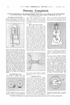
AnImpromptu Jack.
L. Joseph, No. 18,601, dated 13th August, 1912.—A suitably curved block
or skid is strapped on to the rim of the wheel, as shown in the accompanying drawing, when it is desired to lift the wheel clear of the ground for any pur
pose. This arrangement is very convenient when fitting a Stepney spare wheel, as the block is no wider than the tire which is resting upon it and does not, therefore, interfere with the auxili. ary wheel.
Shock-absorbing Clutch.
S. I. Prescott, No. 11,336, dated 13th May, 1912.—In this clutch two separate frictional driving surfaces are used. The first takes the form of the ordinary cone clutch mounted on the flywheel, but with the male member not mounted direct on the driven shaft. It is hero mounted on a sleeve which surrounds the driven shaft, and it has a helical groove formed inside it. Mounted on a squared portion of the driven shaft is a worm having an external thread fitting the thread on the inside of the sleeve ; a spring between the worm and the end of the sleeve holds the two members in frictional engagement along the thread, so that the sleeve drives the worm and through it, the shaft. The torque transmitted by this part of the clutch increases as it is moved along the sleeve, and so compresses the spring owing to the increased pressure between the surfaces. When the main clutch is let in, the sleeve rotates but does not drive the worm, causing it instead to travel longitudinally, so that the pres
sure on the friction surfaces increases, and the load is taken up slowly and progressively.
A Magneto Drive, Firm of Robert Bosch, No. 23,046, dated under the International Convention, 3rd May, 1912.—This specification describes an improved method of driving magneto armatures of the type in which the armature is oscillated about a normal position. Hitherto the return springs have been directly coupled to the deflecting lever, but according to this invention a rocking member is introduced between the spring and the lever. In the construction illustrated, this, rocking member is formed as a T-picee having no definite pivot point. It is hinged at one end to the lever on the armature shaft, and rocks about a stationary seat. The rocking piece is coupled to a spring, so that any movement of it compresses the spring. By suitably proportioning the parts the drive given to the armature may be varied to a considerable extent. The motion of the various parts may be made a purely rolling one, so that :anooth working is ensured and friction is avoided. Various modifications are described and illustrated in the specification.
The Latest %styles Motor Plough.
A. Wyles, No. 4930, dated 28th February, 1912.—According to this invention the driving wheels of motor ploughs or other agricultural implements are arranged so that they may be raised and lowered relatively to the frame of the machine. This is accomplished by mounting them on arms which are radial to a shaft through which the drive is transmitted to the wheel. The accompanying illustration shows diagrammatically one form which the invention may take, but it can be applied to any type of transmission. A hand wheel is provided for raising and lowering the wheel by means of a rack and pinion. [We
described this plough fully in our issue dated 7th November, 1912, pp. 294-7.--. ED, ]