


Typical Business Motors for Heavy Loads.
Page 5
Page 6
If you've noticed an error in this article please click here to report it so we can fix it.
The "J. & B..-Lacre" 3-ton Chassis.
This 3-ton van or lorry chassis was introduced to the commercial motoring world at the Olympia Show, last March, by the Lacre Motor Car Co., Ltd., of Poland Street, London, W., and it has undergone severe testing, and has been much improved, since the first chassis was rushed through the works in time for the exhibition. Our readers will remember that we briefly described this vehicle in our report of the show (see this journal for the lii.th of March last), and, now that the machine has been thoroughly evolved to the marketing stage, we are happy to present some additional details, together with illustrations from photographs which have been specially taken for reproduction in the columns of "Ts COMMERCIAL MOTOR."
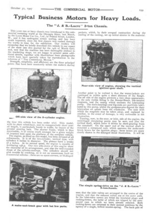
Strength, simplicity, and efficiency are the three principal points that have been constantly before the makers during the time time this vehicle has been under trial. This model, with its short wheel-base, and its comparatively short overall length, is particularly handy in traffic, by reason of the greater steering lock. The shorter frame, which is thus permissible, is of course much stronger for a given weight of imposed load upon the platform of the complete vehicle. The engine, as fitted on this model, has been stripped of all refinements. It is of the two-cylinder, vertical type, with cylinders 6 inches in diameter. The pistons have a stroke of 5 inches. At its normal speed, the engine is capable of developing 25h.p. Our two side-views of this engine show the character of its arrangement, and also the well-rounded shape of the cylinder-castings. The cylinders should not give trouble by cracking, as is not an uncommon fault on commercial vehicles : there are no spare corners, or ill-shaped pockets, which, by their unequal contraction during the cooling of the casting, set up initial strains in the material.
Another point to be noticed is that the water-jackets are continued to within quite a short distance of the flange. The off side of the engine presents a very clean appearance, as the only visible fitting is the Simms-Bosch, low-tension magneto, and the casing which encloses the lubricating pump. The main-bearings and big-ends are positively lubricated by this pump, whilst the gudgeon-pins depend for their lubrication on splash from the crankcase. The ease with which the magneto may be taken away, and replaced by another, in the event of damage, is very noticeable in the illustration.
Turning, now, to the near, or inlet, side of the engine, the centrifugal circulating pump may be seen, and also the vertical shaft, which latter is driven by skew-gearing from the camshaft. On the upper end of the vertical shaft is mounted a compound cam, which operates the make-andbreak levers for the ignition plugs : these levers are more clearly shown in the enlarged detail illustration. It will be seen that the inlet valves are arranged in the centre of the engine, and that the exhaust valves are at the outer ends. In the inlet-valve covers are fitted the insulated plugs ant rocking-levers, the latter of which are tripped by the compound cam to which we have already referred. Both rocking-levers are returned to their normal positions by the agency of a single, helical tension-spring. The back pair of
valve-covers is clamped down by a yoke-piece, as shown in the detail view of the ignition cam. The crankshaft, main bearings are contained within the upper part of the crankcase, as is now the general practice. We give a view of the crankcase, the lower part of which has been removed so as to show the shafts, timing-wheels, and the skew-gearing by which the vertical-shaft is driven. The whole of these parts are completely enclosed by the bottom part of the case. The generous proportions of the leather-faced, cone clutch are also well hown in the crankcase illustration, and it will be noted that all the clutch gear is mounted on an extension of the crankshafl, complete as one unit.
The control of the engine is effected by a foot lever, mounted near the steering column, and acting in conjunction with a centrifugal governor. The timing of the ignition remains constant for all speeds of the engine, a practice which has become fairly general whenever a low-tension magneto is employed on a chassis.
The carburetter is of the float-feed, automatic type, and it is fed by gravity from a petrol tank, the capacity of which tank is sufficient for a journey of about So miles.
The arrangement of engine and steering gear on this chassis is such that the driver is seated by the side of the engine. There is no dashboard behind the engine; there is, instead, a large, tram-type screen, which affords ample protection for the driver's legs. This is hinged in such a manner that the screen, together with the leading-wheel wings, may be swung forward, and out of the way, when the driver desires to do anything to the engine, or to any part of the machinery contained within the bonnet.
Between the clutch and the gear-box, a universal coupling
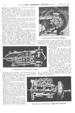
The change-speed gear-box, as illustrated on this page, is of the always-inmesh type. The three forward and one reverse speed-gears are brought into operation as required by the dogclutches which are clearly shown in the illustration. In the same casing is enclosed the bevel-driven, differential countershaft, and it will be observed that all the.shafts are mounted on ball bearings, with ball-thrust bearings to take all endthrust due to the bevel-drive, or to the clanging of the gears.
Two, powerful, independent brakes are fitted : the foot-brake operates on two drums which, together With the chain: Sprockets, are mounted on the outer ends of the differential, countershaft. . One, of
these drums, With its brake-blocks • • • and operating levers, is shown on this page. The simple but quick and effective, adjustment of the foot-brakes is a strong point on this vehicle, and the method of effecting the adjustment is well shown in this illustration. The sidelever, or hand, brake acts directly on the rear wheels, by means of internal, expanding blocks.
The length from the back of the driver's seat, to the extreme rear of the chassis, is if feet, this being ctrRicient for any type of body wi"_in the load capacity of the vehicle. Its overall length, due to the disposition of the engine, is considerably less, for such a platform area, than is the case with the average chassis of the same capacity. The artillery-pattern, road wheels are built to take 34-inch by 4-inch, De Nevers, . grooved, solid tires. The wheel-g-auge is 5 feet, whilst the wheel-base is to feet, The frame is 40 inches wide. The general appearance of this make of vehicle, fitted with a tilt van body capable of accommodating a load of 3tons, is shown by our illustration on page 205. The machine there shown is one which has Clone Much hard work; and is reproduced from a photograph taken of the van during the time that it was employed by Liptons, Limited, for demonstration purposes.