


With Intent to Improve.
Page 22
If you've noticed an error in this article please click here to report it so we can fix it.
A Weekly Summary of Recent Patents, of Interest to the Maker and User of Commercial Motor Vehicles.
Selected and Abridged by H. S. Hall, A./41.I.A.E.
A Ford Steering Gear.
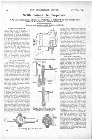
The National Manufacturing Co.'s steering gear, which is described in specification No. 103202, is designed, in the first place, so as to be apt:likable to a Ford chassis, its principV feature being that of irreversibility, which iS lacking in the standard,Ford gear. The patentees make it clear, however, that the gear is meant for general use.
As will be gathered from our illustration, the orcEnarci steering shaft terminates in a giobe, in which is cut a deep spiral groove. The steering arm is designed sb that its inner end envelops rather more than half of this globe, and a stud, screwed, into the steering arm, engages with itS free god into the spiral groove on the ball end of the steering shaft. Rotary motion of the steerFrig shaft, in .consequence, cailoes angular movement in a plane determined by the position of:the stud on the arm.
A Magneto Protector.
The Sunbeam Motor Car Co., Ltd., and L. Coatslen, of Moorfield Works, Wolverhampton,in specification No. 105,374, describe a patent cover for protecting a magneto. from the ingress of dirt and moisture. In the main, this. protecting cover consists Of metal walls solid with the bracket upon which the magneto is carried. These walls •-nay,
of any suitable height, and one of them may be provided with a bearing to carry the short shaft from the magneto driving gear to the coupling, which is in pert attached to the magneto shaft, and in part to this driving shaft. A cover surmounts these walls, 'and this cover again may have other detachable., smaller covers and oiling holes. Our illustration 'is a sectional elevation of one method of carrying out this invention, with a magneto shown in ' place. It will beacon that on three sides of the bracket, upon which the magneto is mounted and integral with it, are
. vertical wails. The end wall is fitted " with a ball hearingfor the driving shaft, -.
and this wall is high enough to coves and protect its bearing. From this end the walls slope downwards, so that at the rear end they are, on the-same level of the Platform, thus affording the maxi
mum of accessibility to the contact breaker at the rear of the flute-net°. Over these walls a main cover is fitted which makes a watertight joint with them.
This main cover is provided with apertures for ignition wires, which apertures are fitted with insulating bushes of such a size that they Op the insulation to the' wiresfirmly, and prevent the ingress of moisture. Oil holes are also provided and temporarily closed by means of screwed plugs. An end cover plate is fitted which allows of ready aceess to the contact breaker.
A small pocket is cast in the platform, as shown, and into this some hygroscopic material, such as calcium. chloride, may be placed, so as to collect any moisture which may be formed by sweating.
There are five claims, the principal ones being the watertight easing comprising a platform having walls to which is attached, more or less permanently, a cover; and a platform having walls, one end of which is high enough to form a protection to the driving shaft and its bearing, but at the other end the walls are low enough to permit easy access to the contact breaker.
TWo-fuel Carburetters.
C. F. L. King, in his original two-fuel carburettor, applied it to that type of petrol carburetter in which main and auxiliary jets are used, the main jet taking its supply of petrol in the ordinary way from the float chamber, the auxiliary jet being fed from a special chamber open to the atmosphere and connected to the petrol supply through a restricted orifice.There is also a compensating jet for starting purposes.
In Mr. King's invention, as it was then applied, paraffin only was supplied to the main jet, and petrol to the other two. In a recent specification, however, No. 105,533, he describes an imProvemont upon his Previous arrangement, whereby paraffin is supplied to the main and auxiliary jets, -and petrol only to the compensatine. jet, -which is generally teed for starling and for slow running. We reproduce two of the drawings which accompany this specification. Two float chambers are provided, the main -One containing paraffin is connected by a passage to time hollow plug shown at•the bottom of the carburetter and disposed centrally with regard to the choke tube. Reference to the drawing will show that paraffin is from this source fed to both the main and auxiliary jets, which themselves are situated within the choke tube, and so far as the operation of paraffin is concerned, the action of these two jets is the same as it is in the ordinary p2troI-using device. A separate chamber, however, is formed in Conner-• lion with the compensating jet, and this is connected only With the petrol Boat chamber.
The arrangement can be gathered by reference to the lower of the two drawings which we reproduce in connection with this specification. It will be seen that the engine suction, when the throttle is only just opened, draws air over the top of a vertical pipe, which, atits lower end, communicates with the petrol float chamber. This has the effect of lifting petrol up the vertical pipe, and a rich mixture of air is admitted to the auxiliarY jet.. The further opening of the• throttle cuts off this supply, so that paraffin only is utilized for the normal running of the engine. .