


A Gearbox with a Silent third Speed
Page 70
If you've noticed an error in this article please click here to report it so we can fix it.
A Résumé of Recently Published Patent Specifications
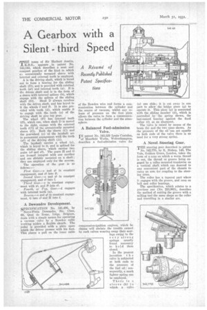
MEER name of Sir Herbert Austin, K.I3.E., appears , in patent No. 343,183, which describes a neat and compact gearbox of the kind in which a,.1. eccentrically mounted sleeve with Internal and external teeth is employed.
A is the driving shaft, which is bored out to form a bearing for the sliding shaft (D), and is provided with extetnal teeth (aI) and internal teeth (a). B is th•I driven shaft and is in the form of a sleeve with internal splines (b), which engage with the splines of the sliding
shaft (D). Shaft D always revolves with the driven shaft, and has keyed to it the wheels f 'and f1 It is also provided with teeth (d), which enable it to engage with the teeth (a) of the driving shaft to give top gear.
The wheel (0.) has• internal teeth '(fl), which can, when shaft D is moved to the right, engage with the external teeth (Cl) of the eccentrically mounted sleeve (C). Both the sleeve (C) and the gearwheel (e) of the layshaft are In permanent engagement with the teeth (al) of the driving shaft (A).
The layshaft carries a wheel (e), which is keyed to it, and is splined for the sliding sleeve, which carries two gedrs (e2 and e3). The gears H and G are focmed integral with one another and are slidably mounted on a shaft; they are employed only for the reverse.
The operation of the gear is as follows
First Gear.—e and at in constant engagement, and e5 into fl.
Second Gear.—e and al in constant engagement, and e2 into f.
' Third Gear.—c in constant engagement with al, and f2 into O.
Fourth, or Top, Gear.—d engages with internal teeth (a).
Reverse.—e and alin constant engagement, G into e2 and H into f.
A Dewandre Development.
SPECIFICATION No. 341,496, by Servo-Frain Dewandre, Ste, Cline, 68, Quai de Rome, Liege, Belgium, deals with a simple means for operating a vacuum valve by a Bowden cable working within a flexible sheath. The pedal is provided with a plate upon which the driver presses with his foot. This places a pull on the inner cable of the Bowden wire and forms a communication between the cylinder and the source of vacuum, whilst any release of pressure on the foot plate allows the valve to form a communication between the cylinder and the atmosphere.
A Balanced Fuel-admission Valve.
IN patent No. 343,329 Louis Coatalen, of Moorfield Works, Wolverhampton, describes a fuel-admission valve for compression-ignition ,engines, which he claims will obviate the trouble caused by such valves wearing away their seatings owing to the very strong springs usually found necessary to h ol.d them closed.
In the present invention t h e valve is subjected at both ends to the pressure. of the fuel oil; consequently, a much lighter spring can be employed.
There is n sleeve (b) in whicha Valve
(a) can slide; it is cut away in one part to allow the bridge piece (g) to operate it. This piece (g) is connected with the sliding member (d), which is controlled by the spring shown, the last-named bearing against the fixed collar (f) as an abutment.
The valve is raised by means of the beam (h) and the two cams shown. As the pressure of the oil canact equally on both ends of the valve there is no need for a very strong spring,
A Novel Steering Gear.
THE steering gear described in patent No. 342,770, by R. Bishop. 145, The Vale, Golders Green, London, takes the form of a cone on which a worm thread is cut, the thread or groove being engaged by a roller mounted Crankwise on a vertical shaft which can descend to any convenient part of the chassis to carry an arm for ,coupling to the steering arms.
The roller has a tapered part where it engages with the groove, and runs on ball and roller bearings.
The specification, which relates to a previous one (No. 223,963), describes the method of cutting the groove with a milling tool the same shape as the roller and travelling in a similar arc.