


A NOVEL FRONT1 -DRIVEN CHASSIS, .
Page 16
Page 17
Page 18
Page 19
If you've noticed an error in this article please click here to report it so we can fix it.
Features Include Low Platform Level,Detacha Change, and Complete Absence of and Transmission Unit, Semi-automatic Gear echanism to the Rear of the Dash.
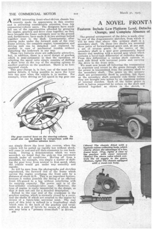
AMOST interesting front-wheel-driven chassis has recently made its appearance in this country and is attracting considerable attention from big commercial-vehicle users. The designers have made full use of the opportunities afforded by grouping the engine, gearbox and drive close together, as they have brought the frame extremely near to the ground and, furthermore, have made it in two sections bolted together hear to the dash. Consequently, after placing jacks under the forward ends of the rear frame section, the complete engine, transmission and driving unit can be detached and replaced by another in case of mechanical trouble without disturbing the bodywork in any way.' These two features alone are sufficiently attractive, but, in addition, there is a novel design of gearbox .which is semi-automatic in that the operation of selecting the speed ratio simply consists of shifting a short lever at the top of the steering cplumn to another position on the quadrant. There is no footoperated clutch.
This gear-Change is, in fact, one of the most fascinating details, it being possible to move the lever into any gear when the vehicle is in motion. For example, when driving at full speed.in top gear one can simply throw the lever into reverse, when the vehicle will be pulled up rapidly but without shock, will come to rest and will then commence to run backwards. During a demonstration which we were accorded, we found that the pick-up was extremely smooth under all conditions. Moving off from a standstill, for example, was simply a matter of shifting the gear lever from neutral to first speed, when the vehicle would get under way smoothly and rapidly.
As will be seen from the photographs and sketches reproduced, the forward end of the frame which carries the engine overhangs the front axle by a distance of about 3?,ft. This is an important feature, because it makes possible the fitting of an efficient front life-guard to a bus without interfering with its carrying capacity. The power unit is of the four-cylinder overhead-valve type. However, the type of engine is really immaterial to the design, so that it does not call for a detailed description.
Bolted to the rear end of the crankcase is the gearbox casting, which is normally closed by a cover, and the shafts of which are coupled to the engine by means of a fabric-type universal joint. The rear part of this joint is splined to a longitudinal shaft which runs to the back of the gearbox and terminates in a pair of bevels by means of which what one may term a "primary cross-shaft" is driven.
B32 The general arrangement of the drive is made clear by one of the diagrammatic sketches, from which it will be seen that above this primary shaft is a secondary. shaft. On these two shafts are mounted three pairs of forward-speed gears and, at one end, a set of reverse gears. In the centre of the secondary shaft is a spur gear permanently keyed thereto and meshing with a second spur wheel which contains a bevel-type differential of orthodox design. From this differential a cardan shaft extends at each side fitted with universal joints and carrying the drive to the frontaxle.
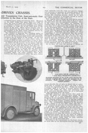
We must now break off following the transmission in sequence and revert to the gears through which the power is transmitted from the primary shaft to the secondary shaft. The gears on the primary shaft are permanently fixed in position, but those on the secondary shaft normally ride freely unless they are brought into action by an ingenious system of internal clutches. Each of the latter gears is built in halves supported by collars on the shaft and screwed together as shown in the sketch, a cylindrical space being left between them. Mounted on the shaft within this space there is a pair of discs, the faces of which are provided. witl_ a series of concentric circular grooves meshing with similar peojections, or rings, cut on the inner faces of the halves of the gear. These halves actually ride on bosses formed on the inner discs, so that they are independent of the shaft unless clutched thereto by the wedge-section grooves and rings. The method of securing this clutching action is both ingenious and effective. A gear-type oil pump is driven off the primary-shaft bevel and continually circulates the oil present in the casing. At one end of the secondary shaft is a neat sleeve valve, by means of which oil under a pressure of two to three atmospheres can be directed to any one of the gears.
To follow out the process, let us assume that the vehicle is at rest with the gear lever in -neutral, the position of the valve then being such that the oil is completely cut off from the gears. Now suppose that the gear lever is moved into the first-speed position, this having the effect of opening ports .which admit the oil to the first-speed gear on the secondary shaft. Oil under pressure then flows between the discs contained within this gear, forces
them outwards until the rings and groove:, engage, and continues to maintain an outward thrust on the clutch members while the drive is being taken up. During this clutching process, which, as we have previously remarked, is extremely smooth in action, the vehicle gradually gets under way.
Now suppose that a. change-up from first to second is desired, all that the driver has to do is to move the gear lever into the appropriate position. Ports in the sleeve valve then admit oil between the coupling discs of the second-speed gear and, at the same time, oil is admitted to the outside of the discs in the first-speed gear. Simultaneously with these operations an exhausting port is opened communicating with the space between the discs of the firstspeed gear. Following out the results of these happenings, it will be understood that the secondspeed clutch engages and takes up the drive, the first-speed clutch_ is freed by the oil forcing the discs inwards and the lubricant which was between the discs of this gear is allowed to escape through the port provided. Without entering into further details, it will be clear that this sequence of events occurs whatever gear it is desired to engage.
As we have not seen the gearbox in pieces we
cannot describe the oil valve in detail, but we understand that it consists of a sleeve cut with a series 1 of ports for regulating the flow. Within the hollowl oecondary shaft is a series of bronze sleeves telescoped one within the other and containing thel ducts and ports through which the oil is 'delivered I to, and exhausted from, the gears.
Although limited in size because they must fit inside the gears, the clutches have stood up/ to severe tests in a very creditable fashion. The designers do not anticipate that wear will be rapid, as the slipping surfaces work in oil and the coupling discs are of hard bronze, working against the steel gear. The workmanship displayed in the gearbox of this chassis is of very high order, and this no doubt accounts in part for its excellent behaviour.
A practical detail which we have not yet mentioned is that the application of the foot brake or hand brake automatically operates a valve which cuts off the oil supply to the gears and so puts the vehicle in neutral. Consequently, so long as the hand brake is on when the vehicle is stationary, no unauthorized person can do any harm by fiddling with the gear lever on the steering column. Furthermore, this system lends itself to easy external control, as will be described later.
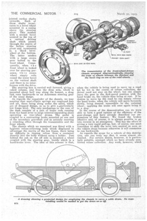
Reverting to the transmission to the front wheels, we must take up our description from the universally 533 jointed cardan shafts onwards. Each of these shafts terminates in a bevel wheel mounted in a casing above the steering pivot: This meshes with a second bevel secured to the top of a vertical driving shaft which passes through the centre of the hollow steering pivotand terminates in a third bevel wheel at the bottom. The latter meshes with a large crown gear bolted to the front wheel. Consequently, when t h e front wheel is locked over for steering purposes, this crown wheel simply rolls round the lower bevel on the vertical shaft and there is no interference with the drive.
The steering box is carried well forward, giving a raked column, and from the drop arm, which is mounted about half way along the bonnet, a drag link runs backwards to an Ackerman steering gear of the usual design.
As regards the remainder of the chassis, we may mention that semi-elliptic springs are employed fore and aft, these being slung under the axles, which are of dropped design, so as to give a,particularly low frame level. The only mechanism to the rear of the dash consists of a pair of brake rods running from the hand lever to large internal-expanding shoes operating on rear-wheel drums. The pedal is coupled to a contracting brake mounted on one end of the secondary gearshaft and so actually exerting a retarding effect through the transmission and the front wheels.
The chassis which we examined was fitted with a hygienic refuse-collecting body which displayed to advantage the merits of the low frame, there being no difficulty in tipping refuse from a container directly into the body without using a ladder. Just behind the cab on the off side is mounted a wheel coupled with the steering gear' beside which is a hand-brake lever. The idea of this scheme is that,
when the vehicle is being used to mpve up a road bit by bit in the course of refuse collection, the driver need not stay at% the wheel, hut can simply leave the gear in the first-speed position with the hand brake on, the vehicle then being at rest. If he desires to move up the road he can simply release the hand brake, when the vehicle will move forwards slowly, being steered meanwhile by the external wheel applying the brake will once again bring it to a slop.
In the course of the demonstration run We were able to form a good opinion of the efficiency of the gear-change and have already described our
pres,sions of this feature. We found the brakes effective and, of course, it is always possible to go into reverse in an emergency. This has the effect of giving a very rapid pull-up, but, of course, one must remember to shift the lever into neutral so soon as the vehicle stops because otherwise it will commence to run backwards.
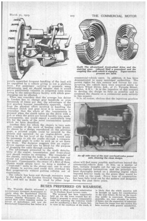
As regards the scope for a vehicle of this description, one can truly say that it seems almost unlimited. For certain duties, however, it is particularly suitable, amongst which we have already mentioned refuse collection. Any work, however, which entails somewhat frequent handling of the load will be expedited by a vehicle giving so low a platform level. For passenger carrying it presents many advantages, and we should imagine that it would prove particularly valuable in congested town areas owing to the extraordinary facility with which gear changing can be effected. , When one considers that the average bus driver in London has to change gear hundreds or even thousands of times per day, the advantages of the new gearbox become immediately apparent. Apart from the physical effort involved in handling the orthodox clutch and gear lever it is necessary to remember that the whole of the transmission is stressed when the clutch takes up the drive with a jerk or when the gears are forced harshly into mesh. Consequently, one would expect a particularly long life for the parts of the novel transmission system which we have described.
Another duty, for which the chassis is very suitable consists of the work of hauling cable drums. As shown by a design reproduced on the previous page, a pivoted cradle could be secured to the chassis and operated by an engine-driven gear. Owing to the low level of the frame, it would only be necessary to tilt the cradle thi oug-h a comparatively small angle in order to pick up or set down the drum. The designer suggests that an enginedriven capstan could also be fitted for the purpose of dragging the cable through conduits. The advantages presented by the teadv detachability of the engine, transmission and front-wheel unit should require no stressing. The remainder of the chassis, carrying the body, is so simple that one would not anticipate any mechanical troubles with this part. Consequently, the owner of a fleet of these ellassis would simply have to keep a number of " front-end" units in the.stores—say, one to every 12 chassis in service—and could then overhaul his fleet progressively without putting vehicles out of commission.
The vehicle has been out through extensive tests in the hands of the London General Omnibus Co., Ltd., and will no doubt be tried by other large commercial-vehicle users. In addition, it has been demonstrated to many municipal authorities. The patent rights for this country and licence for constructing the vehicle have been acquired solely by Modern Wheel Drive, Ltd., of 17, Victoria Street, London, S.W.1. It is the intention of this concern to develop the design as fully as possible and to construct the chassis on a commercial scale entirely in this country. It is, of course, obvious that the ingenious gearbox alone will find many possible applications beyond the commercial-vehicle field. It was, as a matter of fact, initially brought out for use on internal-combustion-engined locomotives, and the principle has been thoroughly tested on a shunting engine which imposed heavier loads on the gears than would be met with on the road. Every item of construction has been fully tried out by the makers and designers during the past three years..