


Speeding-up Pipe-line Maintenance
Page 44
If you've noticed an error in this article please click here to report it so we can fix it.
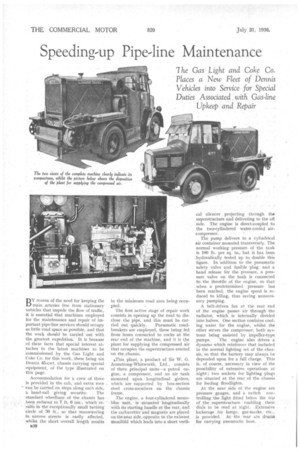
BY reason of the need for keeping the main arteries free from stationary vehicles that impede the flow of traffic, it is essential that machines employed for the maintenance and repair of important pipe-line services should occupy as little road space as possible, -and that the work should be Carried out with the greatest expedition: It is because of these facts that special interest attaches to the latest machines to be commissioned by the Gas Light and Coke Co. for this work, these being six Dennis 45-cwt, chassis carrying special -equipment, of the type illustrated on this page.
• Accommodation for a crew of three is provided in the cab, and extra men , can be carried On steps along each side, a hand-rail giving security. The -standard wheelbase of the chassis hasbeen
reduced to 7 ft 6 whiek re sults in the excePtibnally small turning circle of 30 ft:, so that-'rnanceuvring in narrow -streets is easily effected, whilst theshort overall length results
in the minimum road area being occupied.
The first active stage of repair work consists in opening up the road to disclose the pipe, and this must be car
ried out quickly. Pneumatic roadbreakersare'employed, these being fed from hoses connected to cocks at the rear end of the machine, and it is the plant for supplying the compressed air that occupies the superstructure erected on the chassis,
iThis plant, a product of Sir W. G. Armstrong-Whitworth, Ltd., consists of three principal units—a petrol engine, a compressor, and an air tank mounted upon longitudinal girders, which are supported by box-section steel cross-members on the chassis frame.
The engine, a four-cylindered mono-bloc unit, is 'mounted'. longitudinally with its starting handle at the rear, and the carbnretter and Magneto are placed on the near side; opposite to the exhaust Manifold which leads into a short verti
cal silencer projecting through the superstructure and delivering to the oft side. The engine is direct-coupled to the two-cylindered water-cooled aircompressor.
The pump delivers to a cylindrical air container mounted transversely. The normal working pressure of the tank is 100 lb. per sq. in., but it has been hydraulically tested up to double this figure. In addition to the pneumatic safety valve and fusible plug, and a hand release for the pressure, a pressure valve on the tank is connected to the throttle of the engine, so that when a predetermined pressure has been reached, the engine speed is reduced to idling, thus saving unnecessary pumping.
A belt-driven fan at the rear end of the engine passes air through the radiator, which is internally divided into halves. One section contains cooling water for the engine, whilst the other serves the compressor, both systems being assisted by impeller-type pumps. The engine also drives a dynamo which reinforces that included in the normal lighting set of the chassis, so that the battery may always be depended upon for a full charge. This is, of course, necessary in view of the possibility of extensive operations at night ; two sockets for lighting plugs are situated at the rear of the chassis for feeding floodlights.
At the near side of the engine are pressure gauges, and a switch controlling the light fitted below the top of tbe superstructure ena.bling these dials to be read at night. Extensive lockerage for lamps, gas-masks, etc., is provided. At the rear are driime for carrying pneumatic hose.