


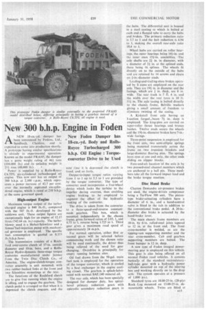
New 300 b.h.p. Engine in Foden
Page 47
Page 48
If you've noticed an error in this article please click here to report it so we can fix it.
ANEW 18-cu.-yd. dumper has been announced by Fodens, Ltd., Sandbach, Cheshire, and is expected to come into production shortly. A prototype having similar specifications is already in experimental operation. Known as the model FR.6/45, the dumper has a gross weight rating of 46+ tons (104,000 lb.) and its unladen weight is
211 tons (48,000 lb:). • • • Power is supplied by a Rolls-Royce C6.TFL six-cylindered turbocharged oil engine. This new unit has an output of 300 b.h.p. at 2,100 r.p.m., which represents a power increase of 42.7 per cent. over the normally aspirated six-cylindered engine, which is rated at 210 b.h.p. at the same governed speed.
High-output Engine
Maximum torque output of the turbocharged engine is 840 lb.-ft., compared with the 547 lb.-ft. developed by the imblown unit. These output figures are exceptionally high for an engine of 12.17 litres (742.64 Cu. in.) capacity. The turbo blower used is a Holset-Schwitzer and a Simrnefuel-injection pump with inechanical governor is employed. The specific fuel. consumption is quoted as 0.355 lb./b.h.p./hour.
The transmission consists of a Rochford over-centre clutch of 17-in, outside diameter and 10-in, bore, and a RollsRoyce Hydro-dynamic three-stage torque converter manufactured under licence From the Twin Disc Clutch Co., of America. The engine-clutch-torque converter assembly is unit mounted, with two rubber-bushed links at the front and two Silentbloc mountings at the rear.
The functions of the Rochford clutch are to give free running when the engine is idling, and to engage the gearbox. The clutch pedal is arranged so that when it is depressed the clutch engages. and the next t:me it is depressed the clutch is freed, and so forth.
Output-to-input torque ratios varying from 1 to I up to 5.3 to I are provided by the torque converter. The type of converter used incorporates a free-wheel device which locks the turbine to the impeller during overrun, thus enabling -engine braking to be employed to augment the effect of the hydraulic braking of the converter.
The drive is taken from the converter to a three-speed-and-reverse constantmesh gearbox. This box, which is mounted independently in the . chassis frame, gives forward ratios of 2.03, 1, and 0.75 to 1, reverse being 1.725 hal. Third gear g:ves a maximum road speed of approximately 24 m.p.h.
For normal operation, either first or second gears will be selected before commencing work and the chosen ratio will be used continually, the driver thus being relieved of the need for gear changing. Overdrive is principally for empty running between sites.
Oil fuel drawn from the 50-gal. main fuel tank is employed for the operation of the torque converter, which is cooled by a heat exchanger in the engine cooling circuit. The gearbox is splash-lubricated with normal SAE.140 mineral oil.
The rear axle, which has been specially designed for dumper duty, has spiralbevel primary reduction gears With epicyclic secondary reduction gears in the hubs. The differential unit is housed in a steel casting to which is bolted at each end a flanged Labe to carry the hubs and brakes. The primary reduction ratio is 3.7 to 1 and the hub reduction is 4.94 to 1, making the overall rear-axle ratio 18.4 to 1, .Wheel hubs are carried on roller bearings, the outer bearings being 144-in, and the inner ones 151-in. assemblies. The axle shafts are 2/ in. in diameter, with a diameter of 21 in. at the splined ends, there being 16 splines. The wheels fit directly on to the outside of the hubs and are retained by 14 screws and cleats on 1-in.-diameter studs.
Leading-and-trailing-shoe brakes operated by S cams are employed on the rear axle. They are 19f in. in diameter and the facings, which are + in. thick, are 8 in. wide. The rear track is 7 ft. 4 in. and the width over the rear tyres is 10 ft. 111 in. The axle casing is bolted directly to the chassis frame, Belville washers giving a small amount of freedom to elfminate twisting of the casing.
A Kirkstall front axle having an 1-section. forged „beam 71 in. deep is employed. The king-pins arc carried on taper-roller thrust bearings and bronze bushes. Twelve studs secure the wheels and the 19f-in.-diameter brakes have 7-in.wide facings.
Three-point suspension is employed for the front axle, two semi-elliptic springs being mounted transversely across the frame on two trunnion brackets and large-diameter floating pins. The springs have eyes at one end only, the other ends sliding on slipper blocks.
Fore-and-aft location of the axle is by two pressed-steel channel members which are anchored to a ball pin. These menihers take all the forward impact load and the brake torque reaction.
Disc Hand Brake
Clayton Dewandre air-pressure brakes are used, the engine-driven compressor being a Tu-Flow 500 unit. The pistontype brake-actuating cylinders have a diameter of 6 in., and a hand-control valve is fitted in the cab in addition to the conventional brake pedal. A 20-in.diameter disc brake is actuated by the hand-brake lever.
The main chassis frame members are 18-in. by 6-in, rolled-steel joists tapered to 12 in. at the front end. The front cross-member is welded, as are the tipping-ram supporting member and the rear cross-member. Cab and gearbox supporting members are bolted. The front bumper is 12 in. deep.
A new type' of Foden integral powersteering gear is employed on this vehicle. This gear is also being offered on all normal Foden road vehicles. It consists basically of the standard recirculatory-ball-type gear with a hydraulic power cylinder mounted on top .of the steering box and working directly on to the drop arm. The system operates at a pressure of 1,000 p.s.i.
Standard tyres are I8.00-25-in. (28-ply) Rock. Lug mounted on 13.00-25-in. demountable wheels. Twins are fitted at the rear. Each tyre has a rating of 17,500 lb.
Welding is employed throughout the assembly Of the 18-cu.-yt body, which weighs 51 tons. Themain framework consists of . 7-in. by 5-in, pressed-steel channel members and the floor is of sandwich 'construction, with a -A-in. steel bottom plate, 14-in. oak planking and *-in., top Plate_ Side members are thick and all the plate is of a special material developed to resist abrasion and to he highly resistant to indentation.
A protective canopy extends over the cab. As an alternative to the double floor a single }-in.-thick plate floor can be provided. This is reinforced by 3-in. by 3-in, angle iron and is more suited to hard-rock working, the smooth sandwich floor being intended for more general conditions.
The fully enclosed all-steel cab has left-hand steering and the adjustable driving seat is mounted on a spring base. A heater and demister is fitted.
A Hamworthy pump operates the single double-acting tipping ram, with steel piston rings. This ram works on a pivot beam which has guide rails to lift up the body. The time taken to tip to 65is eight seconds, whilst the power return takes five seconds.
The FR.6/45 dumper has a wheelbase of 13 ft. 6 in. and an overall length of 26 ft. 4 in. The overall width is 11 ft. and the overall height to the top of the canopy is 12 ft. 71 in., or 20 ft. 2 in. when fully tipped. The clearances under the front and rear axles are 1 ft. 6 in. and 1 ft. 4 in. respectively. The laden rear axle loading is 311 tons (70,000 lb..