


Multiple-Disc Clutches.
Page 17
If you've noticed an error in this article please click here to report it so we can fix it.
With Special Reference to the Very Successful Type Made by the British Hele-Shaw Patent Clutch Company.
Mr. Thomas J. Fay, the president of the American Society Automobile Engineers, in a paper on clutches which he :ad a few months ago, stated :—
" The temptation is to champion some particular type. his temptation is dictated, perhaps, by limited experience. one becomes accustomed to the use of one type it naturly influences his inclinations, and he ultimately arrives : a point where he is blind to the perfection of types with !licit he has had the least to do. It is not too much to iy, that of all the types of clutches known in connection ith the motorcar, not one is so inferior as to fail to work it is properly designed. It is proper to point out, ierefore, that, in service, clutches may be of any type and ill be so good as to be commendable." It must not be tderstood, therefore, that in bringing to our readers' notice .e latest form of the Hele-Shaw clutch, that we favour that pe to the exclusion of all others.
Since Dr. H. S. Hele-Shaw, F.R.S., in 1903, described s invention at a meeting of the Institution of Mechanical ngineers, its reputation has steadily increased, and to-day is being manufactured, in large numbers, in England, rance, Germany, Belgium, and the United States of rnerica. Many multiple-disc clutches are made and offered " our own patented form of multiple-disc friction clutch," Lt it is safe to say that there is not one of these which gives ch uniformly good results as that made by the British Helelaw Patent Clutch Company, Limited, of Chatham Street, .verpool. Like all other forms of lubricated clutches, bower, it requires to be thoroughly understood by both the otor manufacturer and the user. Differences of tempera. re affect its working ; the thickness, or rather the viscosity, the oil which may be used during the winter months ust, therefore, not be so great as that of the oil which employed when warmer weather prevails. An oil that is
a from all " greasiness " should be used, that is to say, rhould not contain any animal or vegetable fats and it uld possess, to a great extent, the power of conducting heat which is generated by the friction of the plates. 'he only parts of the plates in a Hele-Shaw clutch which r conic into frictional contact with each other are the
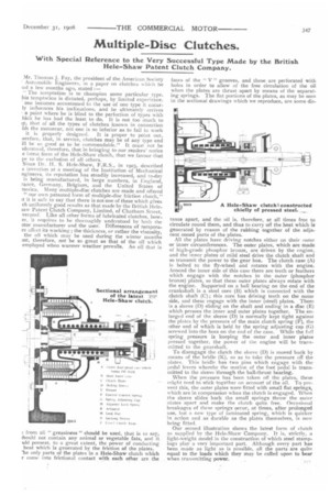
faces of the " V " grooves, and these are perforated with holes in order to allow of the free circulation of the oil when the plates are thrust apart by means of the separating springs. The flat portions of the plates, as may be seen in the sectional drawings which we reproduce, are some dis tance apart, and the oil is, therefore, at all times free to circulate round them, and thus to carry off the heat which is generated by reason of the rubbing together of the adjacent coned parts of the plates.
All the plates have driving notches either on their outer or inner circumferences. The outer plates, which are made of high-grade phosphor bronze, are driven by the engine, and the inner plates of mild steel drive the clutch shaft and so transmit the power to the gear box. The clutch case (A) is bolted to the fly-wheel and rotates with the engine. Around the inner side of this case there are teeth or feathers which engage with the notches in the outer (phosphor bronze) plates, so that these outer plates always rotate with the engine. Supported on a ball bearing on the end of the crankshaft is a steel core (B) which is connected with the clutch shaft (C); this core has driving teeth on the outer side, and these engage with the inner (steel) plates. There is a sleeve (D) sliding on the shaft and ending in a disc (E) which presses the inner and outer plates together. The enlarged end of the sleeve (D) is normally kept tight against the plates by the pressure of the main clutch spring (F), the other end of which is held by the spring adjusting cap (G) screwed into the boss on the end of the case. While the full spring pressure is keeping the outer and inner plates pressed together, the power of the engine will be transmitted to the gearshaft. To disengage the clutch the sleeve (D) is moved back by means of the bridle (K), so as to take the pressure off the plates. This bridle has two pins which engage with the pedal levers whereby the motion of the foot pedal is transmitted to the sleeve throughthe ball-thrust bearing.
When the pressure has been taken off the plates, these might tend to stick together on account of the oil. To prevent this, the outer plates were fitted with small flat springs, which are in compression when the clutch is engaged. When the sleeve slides back the small springs throw the outer plates apart and make the clutch quite free. Occasional breakages of these springs occur, at times, after prolonged use, but a new type of laminated spring, which is quicker in action and as durable as the plates themselves, is now being fitted.
Our second illustration shows the latest form of clutch as supplied by the Hele-Shaw Company. It is, strictly, a light-weight model in the construction of which steel stampings play a very important part. Although every part has been made as light as is possible, all the parts are quite equal to the loads which they may be called upon to bear when transmitting power.