


Rolls-Royce Opposed-piston Engines
Page 41
Page 42
Page 43
If you've noticed an error in this article please click here to report it so we can fix it.
for Commercial Vehicles
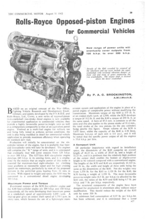
BASED on an original concept of the War Office, Fighting Vehicle Research and Development Establishment, and jointly developed by the F.V.R.D.E. and Rolls-Royce, Ltd., Crewe, a new series of opposed-piston twin-crankshaft two-stroke diesel engines is now available for experimental application to commercial vehicles; they provide a highly favourable power-to-weight ratio as well as a compactness comparable to that of an equivalent petrol engine. Evolved as a multi-fuel engine for military use and being fully tested in arduous service conditions, the unit is also being modified in detail for commercial-vehicle application to provide maximum efficiency when operating on standard dery fuel.
Production will initially be concentrated on the sixcylinder version of the engine, but it is probable that fourand five-cylinder units will later be developed. The engines will comprise the " K " range of units, and it is anticipated that eventually they will cover outputs from 120 b.h.p. to over 300 b.h.p. The 6.57-litre 1(60 six-cylinder engine develops 240 b.h.p. in its existing form, and it is emphasized by the makers that an engine power of this order is essential for maximum-load eight-wheelers for climbing steep gradients at reasonable speed and for high cruising speeds on motorways, particularly in view of the proposed increase in the permitted gross loading from 24 tons to 26 tons. With regard to weight and space, the K60 may be compared to a conventional diesel engine developing 169 h.h.p.
Maximum Power and Torque
Provisional outputs of the K50 five-cylinder engine and the K40 four-cylinder engine are 200 b.h.p. and 160 b.h.p. respectively, all the units developing their maximum power at a crankshaft speed of approximately 2,400 r.p.m. A step-up gear gives an output shaft speed of 3,750 r.p.m. in every case, which favours the use of a lightweight trans mission system and application of the engine in place of a petrol engine of comparable power without modifying the transmission. Maximum torque of the 1(60 is 375 lb. ft. at an output-shaft r.p.m. of 2,500, whilst the 1(50 develops a torque of 312 lb. ft. and the K40 a torque of 250 lb. ft. at the same speed, A bore of 87.3 mm. is common to all the units and this also applies to the piston strpke of 91.4 mm., the total stroke of the two pistons (in the one cylinder) being double this figure. Swept volume of the K50 is 5.475 litres, whilst the capacity of the K40 is 4.38 litres. Maximum b.m.e.p. of each unit is 111 p.s.i., and it will he noted that the specific power output of all the engines is 35.6 b.h.p. per litre.
A Compact Unit
Of particular importance with regard to installation space, the dimensions of the K60 comprise an overall length of 46.25 in., a width of 28,45 in. and a height of 32.25 in., and it is pertinent that the relatively high position of the output shaft enables the bonnet or engine-cover height to be reduced compared with a conventional engine. The lengths of the 1(50 and K40 are respectively 41.125 in. and 36 in., the width and height of these units being the same as the dimensions of the K60. Net dry weights vary from 1,570 lb. for the K60 to 1,120 lb. for the K40, the K50 having a weight of 1,350 lb. The most favourable power-to-weight ratio (6.5 lb. per b.h.p.) is afforded by the K60 unit, the ratios of the 1(50 and 1(40 being 6.7 lb. per b.h.p. and 7 lb. per b.h.p. respectively.
The structural components of the engine have been designed for production in aluminium alloy without major modification. This should reduce the weight of the K60 unit by some 300 lb.
A minimum fuel consumption of 0.37 lb. per b.h.p.-hr. has been achieved, and it is anticipated that a lower consumption on the road in terms of m.p.g. will be obtained by virtue of the unit's operating characteristics than is indicated by this laboratory test figure. A "fiat" fuel consumption curve is a notable characteristic of the engine, the maximum consumption at the limits of the curve being of the order of 0.41-0.42 lb. per b.h.p.-hr.
Although there are two crankshafts per engine and two piston/connecting-rod assemblies per cylinder, the design of the units obviates the use of camshafts, tappets, push-rods, rocker arms, valves and springs, and there are, therefore. .far fewer moving parts than in conventional poppet-valve engines. It is pointed out by th'e makers that the natural balance of the opposed-piston engine combined with robust construction affords scope for raising the power output by increasing the crankshaft speed. The low b.m.e.p. of 111 p.s.i. and the moderate mean piston speed of 1,440 ft. per min. (at an approximate crankshaft speed of 2,400 r.p.m.) of the existing power units indicate that higher crankshaft r.p.m. and b.m.e.p. ratings are well within the capabilities of the engine. Although the ultimate poten
tial of the K60 is not yet known, over 300 b.h.p. may well be achieved without appreciably increasing bulk or weight.
The Roots type scavenge blower of the K60 has a capacity at maximum engine output of 900 cu. ft per min. and absorbs about 40 b.h.p. The eventual application of turbocharging is envisaged, and this will enable a smaller scavenge blower to be employed. The resultant increase in b.m.e.p. will therefore be accompanied by a reduction in the power consumption of the blower.
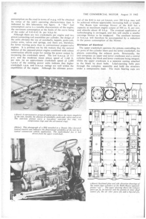
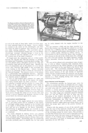
Division of Control The upper crankshaft operates the pistons controlling the air ports of the cylinder liners and the lower crankshaft, the pistons controlling the exhaust ports. Structurally, the unit comprises an upper and lower crankcase and a central cylinder block, the block and lower crankcase being integral, whilst the upper crankcase is a separate casting attached to the block by short bolts. Load-carrying bolts pass through the complete assembly and hold the structure under a compressive load. The main bearing caps are
secured to the ends of these bolts, which therefore carry the main explosion loads of the engine. Injector nozzles are located in the centre of the centrifugally cast liner and locate the liners in position, thus allowing for expansion under running conditions. The crankshafts are of high-quality, nitride-hardened forged steel, and one Holset viscous-type torsional vibration damper is fitted to the upper crankshaft and two dampers of the same type to the forward end of the loWer crankshaft.
Of forged steel, the connecting rods are drilled axially between the big-end and little-end bearings to facilitate lubrication and, if necessary, to provide piston cooling. The cast-iron pistons carry a two-piece cast-iron fire ring, two compression rings and two oil control rings. Because the force of compression acts on the pistons on every inward stroke, their relatively high weight is not converted into inertia loading on the big-end caps. Indeed, increased weight is an advantage in that it assists the lubrication of the little-end bearings. The concave crowns of the pistons give a substantially oval combustion chamber. Injectors are of the conventional single-hole type and a C.A.V. jerktype injection pump is employed.
A train of wide-toothed gears connects the upper and lower crankshafts at the rear of the engine, the output shaft being located above the lower crankshaft. Crankshaft phasing is variable and this enables the torque characteristics of the engine to be modified within limits to suit individual requirements. Mounting the gear train at the rear reduces torsional vibrations, and the size of the gears largely obviates noisy operation resulting from torsional vibration. The blower is driven by a long quill shaft which passes through the centre of the driving rotor and affords a natural frequency of torsional vibration of the system below the tick-over speed of the engine.
Lubrication and Gaoling Other features of the engine include dry-sump lubrication; a wet-sump system will be available in due course. A centrifugal coolant pump, mounted at the forward end of the engine, is driven from the end of the supercharger shaft and acts as a damper on the blower mechanism. Speed-limiting or governor devices are available to suit most requirements. Three-point flexible engine mountings are employed.
The results obtained in military service give promise that the engine will operate for longer periods between major overhauls and between injector changes than a conventional diesel engine. Overhauling does not present any particular problems, and it is notable that the liner ports can be easily cleaned with the engine installed in the vehicle.
For test purposes a K60 unit has been installed in a Dennis Max tractor, and although this vehicle has not been operated for a sufficient time for comprehensive running data to be obtained, performance characteristics of the unit tend to confirm results obtained in military service. A representative of The Commercial Motor who travelled a short distance in the cab of the vehicle states that, although the noise level was normal, the engine operated virtually without detectable vibration throughout the entire speed range.
The unit will be offered with conventional types of gearbox or with an Allison Torqmatic fully automatic transmission (produced by the Allison Division of the General Motors Corporation) of the type fitted to the Dennis Max tractive unit. This transmission essentially comprises an hydraulic torque converter and four planetary gear trains, whilst special features of the unit include an hydraulic vehicle retarder located between the converter and the gear assembly. Of the lock-up type, the converter automatically operates as a fluid coupling during ratio changes, thus cushioning shock loads.
Gear Ratios and Ranges The transmission provides six forward gear ratios (in addition to reverse) and these are divided into four ranges. The normal driving range comprises the third, fourth, fifth and sixth ratios and in a typical application the system is modified to restrict operation to this range to limit the maximum torque that can be transmitted through the final drive. The other ranges give automatic operation between gears one and two, three and four or three and five. According to the maker's description of the unit, the hydraulic control system is triggered by the brain of the automatic transmission—the valve body. This system automatically senses and co-ordinates range selection, accelerator position, engine speed and vehicle speed, and it selects the proper gear ratio at the precise moment of demand.
Integral with the annulus of one of the epicyclic gear trains, the rotor of the hydraulic retarder acts as a paddle wheel when fluid is introduced into the casing, circulation of the oil being resisted by stator vanes. This provides a considerable braking force but as soon as the fluid is evacuated from the casing, the, rotor ceases to absorb power. A measure ef the braking force available is shown by the power absorbed at 34 m.p.h. in fourth gear, which is the equivalent of over 400 b.h.p.