


Another Opposed-piston Engine
Page 54
If you've noticed an error in this article please click here to report it so we can fix it.
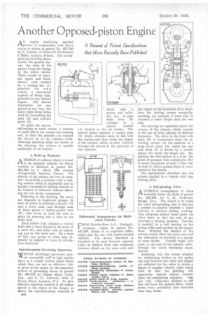
ANengine employing opposed pistons in conjunction with sleeve valves is shown in patent No. 453,740 by E, Schmid, of Usines de Roulements
Billes, Annecy, France. The accompanying drawing shows clearly the general layout, the basis of the patent being the design of the sleeve valves. These consist of separate upper and lower sleeves, each worked by a rocking bar (1) attached to two cranks, a movement capable of being compounded to any desired degree. The sleeves themselves are not ported in any way, the inner edges alone being used for controlling the inlet (3) and exhaust ports (2).
To make the sleeves self-sealing to some extent, a number of small slits is cut around the working end, so that the pressure can expand the sleeves on to the cylinder walls. Although sparking plugs are shown in the drawing, the scheme is equally applicable to oil engines.
A Built-up Radiator,.
ADESIGN of radiator which is slated to be specially suitable for heavy vehicles is disclosed in patent No. 453,398 by C. Mical, 160, Avenue d'Argenteuil, Asnieres. France. The objects of the scheme are two in number—to provide a radiator with a cooling surface which is adjustable and to enable a damaged or leaking element to be isolated or removed without affecting the rest of the component.
Referring to the drawing, the tubes are disposed in single-row groups, to each of which is attached a header (3) also a lower tank, and through each of these passes a hollow-ported bolt (2) ; this serves to hold the unit in place by screwing into a boss on the main tank: Each hollow bolt contains a central bolt with a head shaped in the form of a valve (1), and fitted with an adjusting nut on the outer end, By a turn of this, any group of tubes may instantly he isolated or have its circulation restricted.
Injection-pump Governing Apparatus.
WWHILST centrifugal governors operate reasonably well at high speeds, there is a certain critical speed below which they are not so effective ; this is given as the reason for the improved system of governing shown in patent No. 453,710 by Simms Motor Units, Ltd., and S. II. Attwood, r both of Gresse Street, London, W.1. To give effective injection control at all engine speeds is the object of the design, in which the injection-pump rack-rod is
B44 fitted with a . piston and cylinder (3). A pipe leads from the cylinder to a special venturi (1) located in the air intake. The control pedal operates a conical plug (2) which obtrudes more or less into the v.enturi and thus varies the degree of the suction, which, in turn, controls through the piston 3, the quantity of fuel injected.
Differential Arrangements for Multiwheel Vehicles.
FROM Daimler-Benz A.G., Stuttgart, Germany, comes, in patent No. 453,838, details of an improved differential gear for use with multi-wheeled vehicles. The device described is intended to be used between separate axles, as distinct from that employed between wheels on the same axle, and
the object of the invention i to.distribute the driving torque unequally, enabling, for example, a front axle to transmit a lesser torque than the rear axle.
The drawing we reproduce shows the essence of the scheme, which consists of the use of bevel pinions of different diameters. The drive to the front axle shaft (5) is transmitted from the revolving carrier, via the medium of a large bevel wheel (4), whilst the rear axle shaft (1) is driven by a smaller pinion (2) inside the larger one. Regarding the dual pinion as a lever, the point of pressure (the central pin (3)) is nearer the pinion of shaft 1 than that of shaft 5, thus a greater force is transmitted to the former.
The specification describes also the scheme applied to a vehicle with four driving axles.
A Self-grinding Valve.
A CURIOUS arrangement of valve Pi assembly forms the basis of patent No. 453,201, by S. K. TerkeIsen, Bangil, Java. The object is to make the valve self-grinding, and to this end a scheme is adopted whereby a, slight rotation is induced during working. This comprises helical vanes under the valve head, so that the rush of gas exercises' a turning moments Friction is avoided by a ball bearing on the spring collar and another on the tappet head. Whether the benefits of the scheme would offset the extra cost and the difficulties of assembly is a matter of some doubt. Trouble might also arise, in the case of the exhaust valve, through the vanes becoming incandescent,
Assuming that the means adopted for minimizing friction at the spring cup and between the valve and tappet are sufficient for the valve to attain a degree of angular velocity while raised from its seat, the grinding will apparently depend almost entirely upon the momentum acquired. One can only conjecture whether or not this will have the desired effect. There seems every possibility that excessive wear may occur.