


HALLEY'S NEW
Page 39
Page 40
If you've noticed an error in this article please click here to report it so we can fix it.
" CONQUEROR "
BUS CHASSIS.
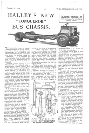
THE successful range of chassis manufactured by Halley Motors, Ltd., Yoker, Glasgow, has just been supplemented by an entirely new four-cylinder bus chassis which has been given the striking name of
"Conqueror." It is designed for bodies carrying from 30 to 36 people on a 16-ft. 3-in, wheelbase and arranged with forward control as standard.
Another chassis similar to the "Conqueror," but equipped with a six-cylindered Dorman engine, type 6 JUL Mark 2, has been named the " Chieftain," but, so far as its own engine product is concerned, the company is pinning its faith to the four-cylindered engine of the "Conqueror," which has proved to be a really noteworthy design and one capable of producing an excellent power output for its size, combined with smooth running and steady pulling on full throttle right down to 370 r.p.m. ,However, before dealing in detail with this unit, we will give a brief description of the whole chassis.
It is designed for single-deckers carrying up to 36 passengers and has an approximate chassis weight of 3 tons 1 cwt. The engine and gearbox sub-frame is three-point suspended on rubber trunnions which are adjustable for wear by squeezing the split housings by pinch bolts, shims being fitted in the first instance to prevent locking.
The main frame has a gradual drop from the dash, is inswept slightly towards the front. arched over the rear axle and dropped again to a lower level at the end. Stout tubular cross-members and a massive built-up member which carries a short central section of the propeller shaft on which is mounted the drum of the transmission brake, serve to give great resistance to frame
twist. The frame has a loading height of 2 ft. and a maximum depth of 9 ins. Only fitted bolts are em ployed in the whole of its assembly.
A single dry-plate clutch is totally enclosed in the bell housing and the drive is taken first through a tubular propeller shaft with large fabric joints, thence via the short shaft to which we have already referred, and, finally, through a tubular section with Spicer universal joints. The whole drive is in line, the engine being raked and the axle slightly tilted.
The rear axle is an inverted-pottype nickel-steel stamping carrying underneath worm gearing of D.R. make.
The rear springs are designed to be fiat under load ; they are 5 ft. 6 ins, long and 4 ins. wide.
The frame arch is fairly long so that wheelbases to suit vehicles 27 ft. 0 ins. or 26 ft. long can be allowed for, the actual lengths of wheelbase being 17 ft. 3 ins. and 10 ft. 3 ins, respectively.
A 35-gallon petrol tank is slung from stout pressed-steel brackets at the off side, but the tank can be extended to hold 45 gallons to meet
special requirements. The spring brackets are bolted right through to the flanges of the tubular crossmembers. Ripault's Alcyl centralized lubrication is provided as standard.
Steering is effected by a Mantes gear. Taper-roller bearings are employed for the wheels and as thrust bearings on the stub-axle swivel pins.
One pair of shoes only is contained in each of the rear-wheel drums, the parking brake operating on the transmission. A tubular cross-shaft mounted on spherical bearings is provided for the foot brake, connection between this and the shoes in the four-wheel drums being effected by steel bands guided over fibre rollers ; the front brakes are the Rubury-Alford and Alder pattern. The operation is through a Dewandre servo. Neither brake is compensated.
Reverting to the gearbox, this Provides four Speeds: Top, direct ; third, L75 to 1; second, 2.98 to 1; first, 4.48 to 1, this is the same as the reverse. At an engine speed of 1,070 r.p.m. and a final-drive ratio of 0.25 to 1, the corresponding road speeds are :-18 m,p.h., 10.8 m.p.h., 6.2 m.p.h., and 4.15 m.p.h., although other axle ratios can be provided.
Exceedingly interesting is the arrangement of the forward control. On the spindle of the change-speed lever are two arms pivoted to a light, triangulated aluminium casting, the end of which carries an adjustable fork or ball connected to a lever on the selector rod. There are so few joints that there is no multiplication of any slackness caused by wear.
Accessibility and ease of main tenance have received their full measure of consideration. For instance, the entire power unit and gearbox can be readily withdrawn with the body in position, it being necessary only to remove the radiator and gearbox cover and disconnect the controls, also the back axle is fully floating and the worm gear and differential can be removed without disturbing the wheels.
The main dimensions of the standard chassis are :—Wheelbase, 16 ft. 3 ins.; track, front, 6 ft. 2 ins., rear, 5 ft. 101 ins.; overall length, 25 ft. 61 ins.; turning circle, 56 ft ; height at rear of frame, 1 ft. 8 ins.; frame length behind dash, 20 ft. 11 ins. ; maximum width, 7 ft. 2 ins.; ground clearance to rear axle, 10 ins.; ground clearance under rear axle, 7 ins. The entire chassis conforms with the regulations of the Ministry of Transport for public service vehicles.
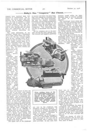
Dealing now with the engine, this is the com pany's design throughout, but embodies Ricardo heads, masked inlet valves, and a siamesed inlet manifold; it also includes a feature which we have for long considered desirable, i.e., centrifugally cast renewable cylinder liners. These are of the wet type, giving an excep tionally large water jacket space and a simple and clean cylinder casting. The liners are pressed in from the top and, at the base, each passes through a Muntz-metal gland ring behind which is a Dermatine stuffing gland. The arrangement permits slight differences of expansion between the cylinder block and the liners. At the top, a flange on each sleeve is wiped with salammoniac before the pressing operation and the cylinders left to age for a week, with the result that the sleeves rust in and become quite water-tight, although there is no difficulty in pressing them out when necessary.
Side valves are employed, each with a double valve spring, and enough metal is left on each seat to permit the insertion of centrifugally cast seats for service replacement, so that the actual cylinder block should never wear out.
The upper half of the crankcase
is carried well below the main bearings, thus making an extremely stiff construction. The three main-bearing caps are massive duralumin stampings, and the main-bearing bolts are extended right through to the cylinder heads, the last-named, incidentally, being in pairs and interchangeable. The connecting rods are also of duralumin with four-bolt caps.
All the cylinders are at the near side, leaving the other entirely free. The dynamo and magneto platforms are east on the crankcase and automatic advance is standard. If a dynamo be utilized, the magneto is put back to the rear platform and driven in tandem. Provision is made for fitting a starter.
Dual ignition can be arranged, a drive for a Delco-Remy distributor being provided at the rear end of the camshaft and a special cover plate provided. In any case, both ignitions would utilize the same sparking plugs to prevent spoiling the shape of the combustion chamber.
The centrifugal water pump has a large vane area permitting thermosiphonic circulation in case of its improbable failure. A yoke piece presses against the neck gland and has a thumbscrew adjustment, the arrangement being similar to that on the Halley subsidy model. Adjustment of the fan drive is effected by a screwed pulley flange.
The timing gear is driven by an adjustable chain with an automatic tensioning device, whilst the magneto is driven by a skew gear from the back of the camshaft chainwheel. The complete magneto drive assembly, with its taper-roller bearings, can be withdrawn b y removing three nuts.
The exhaust manifold leads to the front and has an expansion joint in the middle. The engine breather enters the underside of the crankcase and takes the fumes direct to the atmosphere, whilst a sealed accessible oil filler is brought to the bonnet seat.
The bore and stroke are 41 ins. and 5 ins, respectively, and the b.h.p. is 85 at 2,600 r.p.m.; the peak of the b.m.e.p. being at 1,500 r.p.m.
The sump is jointed at one place only and there are no right-angle joints to make. There is a triple oil seal between the crankcase and the clutch pit, the components of these being a thrower ring, a reverse thread and a knife-edge thrower on the flange for the flywheel.
The crank pins are 2/ ins, in diameter and the total bearing area is much greater than is usual In an engine of this size.
To avoid drumming, the sump is corrugated and internally it is covered by an aluminium plate to prevent the upward splashing of oil. No oil pipes are utilized, the hollow camshaft acting as a distributing pipe to all the main bearings and big-ends.
There are dozens of other interesting features, but, we have not, in this instance, the space to deal with them in detail.