


Patents Completed.
Page 22
If you've noticed an error in this article please click here to report it so we can fix it.
H. L. L. HUDSON, No. 23,435, dated 14th October, 1912.A flexible gearwheel to give silent running is made up of two members, a central rigid hub and a more or less flexible ring carrying the teeth.
Sound-deadening material is interposed between these two members and relative motion between them is limited by tongues on the flexible ring engaging radial slots in the hub. These tongues are secured in place by pins through the hub, and a slight radial movement of the tongues is permitted when the flexible ring is deformed. The maximum deformation permitted is small enough to prevent the teeth coming out of engagement with the other wheel.
J. F. ITEYVAERT, No. 11,229, dated 13th May, 1913 (Patent of Addition to No. 7610/1912).—This invention relates to improved means for mounting mud-guards on the side of a vehicle road-wheel so that they are capable of a swinging movement but yet will not rotate with the wheel. The mudguard itself is composed of a brush portion which is clamped to a bar pivoted at its centre to a short rod ; this, in turn, is pivoted to a lug on a ring fitted to the axle-cap. The axle-cap has a reduced diameter over which the ring passes, and a nut is then screwed on to keep it in position. This nut is prevented from coming unscrewed by means of a pawl which engages with a slot in the axle cap and nut. A spring keeps the pawl in position.
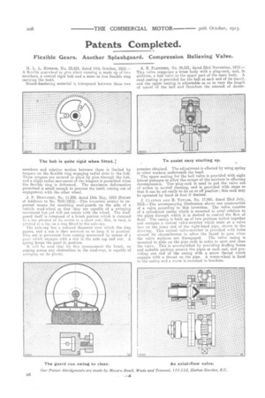
It will he seen that by this arrangement the brush, on coming across any obstruction in the road-way, is capable of swinging on its pivots. A. E. FLETCHER, No. 26,931, dated 23rd November, 1912.— This valve comprises a braes body with a plug-cock, and, in addition, a ball valve in the upper part of the main body. A steel seating is provided for the ball at each end of its travel, and the upper seating is adjustable so as to vary the length of travel of the ball and therefore the amount of deoom
pression obtained. The adjustment is effected by using spring or other washers underneath the head.
The upper seating for the ball valve is provided with eight lateral passages to allow the escape of the mixture in effecting decompression. The plug-cock is used to put. the valve out of action in normal running, and is provided with stops so that it can be set easily to its on or off position; this cock may be operated by hand or foot if desired.
J. CLAYTON AND It. TAYLOR, No. 17,095, dated 23rd July, 1912.—The accompanying illustration shows one construction of a valve according to this invention. The valve consists of a cylindrical casing which is mounted in axial relation to the pipes through which it is desired to control the flow of fluid. The casing is built up of two portions bolted together and contains a conical valve-member which seats on a valve face on the inner end of the right-hand pipe, shown in the drawing. This conical valve-member is provided with holes around its circumference to allow the liquid to pass when the valve surfaces are disengaged. The valve casing is mounted to slide on the pipe ends in order to open and close the valve. This is accomplished by providing stuffing boxes and suitable packing around the pipes at each end, and providing one end of the casing with a screw thread which engages with a thread on the pipe. A worm-wheel is fixed to the casing and a worm is mounted in brackets.