


MAKING BEST USE OF THE FORD.
Page 51
If you've noticed an error in this article please click here to report it so we can fix it.
Valuable Advice on Every Phase of Ford Transport which will Appeal to the Owner, Driver and Repairer.
463.—Curing Front-wheel Wobble.
One of our Lancashire readers recently broke a front spring while on a Jong journey, and a temporary repair was made by fitting a second-hand spring which happened to have very little camber. As a result of this very serious wheel wobble commenced, and it was not arrested until a new spring with the proper camber was fitted. It is suggested, therefore, that a flattened spring may often be looked to as a cause of this trouble.
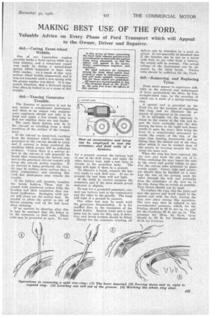
464.—Tracing Generator Trouble.
The dynamo or generator is not by any means a complicated instrument, and there is no reason why maintenance engineers should not take it in hand and apply a few simple tests to find out whether there are any faults.
The most likely defects may be in the cut-out or resulting from a dirty condition of the surface of the commutator.
If the cut-out be suspected, earthing from the terminal which connects the generator to the cut-out should be tried, and if current is being produced the sparking which occurs will be sufficient evidence. Unless there is a serious defect in the cut-out it will generally be found that connecting the battery contact to the generator cut-out contact will bring the cut-out points together. If no current is being. produced, the trouble may be nothing more serious than a dirty commutator, and cleaning this with fine glass-paper may remedy the trouble.
If the failure still persists, examine the brush holders. These may be coated with powdered carbon frean the brushes and their insulation thus rendered ineffective. Syringing with petrol will clean out the carbon dust. Be careful to allow the petrol to dry off before running, and oil the ball races after cleaning.
If no current be showing after this it may be assumed that the defect is in the armature or field coils. These coils may be grounded or open. To test for a ground, connect the battery lead to one of the field wires, and apply the other battery lead, with a test lamp in circuit, to the generator body. The lamp will light if there be a ground.
To discover a break, connect the battery leads to each field wire. If one be present the test lamp will not light.
If the fields be correct examine the armature, and if the mica stands proud undercut it slightly.
To test for a grounded armature, connect one battery lead to the commutator and the other to the spindle. The lamp will light if a ground be present.
On other test may be made with the gener ator disassembled. It is for cracled fibre in the insulation of the brush holder. Battery leads and a test lamp can be used for this, and, if &feefive,, new brush holders should be fitted.
Except for the armature winding, all
defects can be remedied by a good engineer. It can generally be assumed that if the dynamo can be run as a motor with four to six volts from a battery, the output will be normal. The actual voltage of the instrument can be adjusted by the third brush, Twelve volts should be sufficient for the Ford.
465.—Removing and Replacing Tyres.
Some users appear to experience difficulty in the removal and replacement of tyres, particularly the 30-in. by 5-in. straight-sided type, in the securing of which use is made of a spring-retaining ring.
A special tool is provided by the .Ford Co. for the purpose of expanding this ring, and we illustrate the sequence of operations in its removal.
It is advisable for the operator to stand in the centre of the rim and insert the lever vertically into the slot, forcing the lever to the right and downwards to open the jaws; then bring the lever in a semicircular movement towards the centre of the rim, at the same time beating downwards and so lifting clear the slotted end of the ring, after which it can be worked clear of the groove by levering around the rim, using the same tool.
When the ring has been removed, lift the tyre and work the rim out of it. When replacing the tyre, insert the tube in the cover and gently inflate to size. Put the canvas tube protector in place evenly inside. Cover, tube and protector should then be handled as a unit. Lay the rim on the ground, push the valve through the hole and gradually drop the remainder of the tyre on to the rim, doing this as evenly, as possible. Tyre levers should not be used.
To replace the ring, slip the plain end into the groove and work round to the slotted end with the foot, forcing the ring into place during this operation. The tyre may then be inflated to the recommended pressure, which, for the. Dunlop, should be 60 lb. per sq. in., and for the Goodyear 65 lb. per sq. in. The pressure for 30-in. by 3i-in. tyres should be 55 lb. for Goodyears and 45 lb. for Bunions.