


A NEW BOILER FOR . STEAM WAGONS
Page 28
If you've noticed an error in this article please click here to report it so we can fix it.
A Resume of Recently Published Patents.
A most interesting and a novel type of steam genefatorlhaz been patented by F. Lampleugh and O. Is. Lemare, the specification being No 152,392. The inventors state that their object is to provide a generator which will be economical, which will positively prevent the formation of scale and losses in efficiency due to such formation, which will prevent priming, and which will supply steam at high velocity and under high pressure. Briefly, thisaiew generator may be said to consist of a
boiler within a boiler. The outer One, which is calledathe primary generator, makes steam which is not actually used. It is a boiler with no outlet. It contains water which is made into highlpressure steam, the heat of the fira being utilized to maintain it in that condition. The second boiler in reality consists of a coil of tube suspended in the steam space of the first bailer. Water is passed into this coil of tube, and, by the heat of the steam in the first boiler, is, either there cr thereafter, con verted to steam. It is the steam from the secondary boiler which is used in the steam engine. In, view of the fact that the primary generator receives no fresh supplies of water, and may be supplied in the first instance with pure water, there is no scale formed.
The primary generator consists of a furnace or firebox. This is comparatively shallow, and is surrounded by an annular chamber which con tains water. Vertil tubes connect this annular chamber with an upper one of about the same Size and of the same shape. The hot gases from
the furnace are when the hailer is working in normal circumstances, baffled, so that they are diverted outwardly through the lower half of this ring of tubes, then inwardly through the upper half, emerging through a ventral flue which is surrounded by the upper annular chamber of the boiler. They then travel along a passage to. the chimney or other means or exit, There is, as has been stated, no means whereby the steam generated in this boiler can make exit. It is in the upper annular chamber of the primary generator that the secoralary one, which consists of a coil of tubes, is supported. In arrangement and appeiirance generally this unit is strongly reminiscent of the superheater usually fitted to under-tyto steam wagon boilers, except that, of course this generator is disposed in the Steam space, whereas a superheater is placed in the boiler flues. A feed pump, which is part of the equipment, forces wafer at a high pressure into the secondary boiler, through which the water passes at snch a high speed that scale cannot be formed or deposited. Incidentally, owing to the fact that flames or hot gases do not come into contact with the tubes which form the secondary generator, there is no risk of
B18 their corrosion or oxidization; the tube can therefore be made much thinner than would otherwise be the case, and, in consequence, heat passes more rapidly from its external to its internal surfaces.
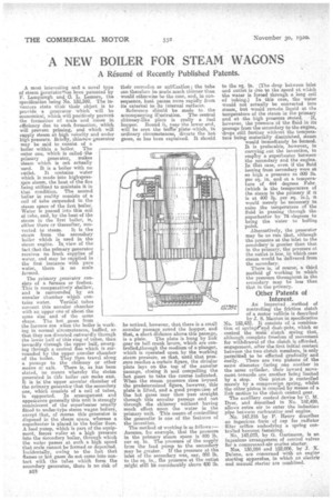
Reference should be made to the accompanying illustration. The central chimney-like piece is eally a fuel hopper. Round it near the lower end,
will be seen the it, .which, in ordinary circumstances, diverts the hot gases, as has been explained. It should be noticed, however, that there is a small annular passage round the hopper, and that, a short dislance above this passage,
is a plate. The plate is hung by link gear on bell crank levers, which are con. trolled,through the medium of a plunger, which is operated upon by the working steam pressure, so 'that, until that pressure reaclies a certain figure, the circular plate lays on the top of the annular passage, closing it and compelling the hot gases to take the course indicated. When the steam pressure rises beyond the predetermined figure, however, this plate is lifted, and a good proportion of the hot gases 'may then pass straight through this annular passage and out through the chimney without having much effect upon the water in the primary unit. This means of controllina the generaror is one of the features of the invention.
The method of working is as follows:— Assume, for example, that the pressure in the primary steam space is 400 lb. per sq. in. The pressure of the supply from the feed pump to the secondary may be greater. If the pressure at the inlet of the secondary was, say, 800 lb. to the sq. in., the pressure at the outlet .might still be considerably above 400 lb. to the sq. in. (The drop between inlet and outlet is due to the speed at which the water is forced through a long coil of tubing.) In this case, the water would not actually be converted into steam, but would remain, liquid at the temperature of the steam in the primary and at the high pressure stated. 'If, however, the pressure of the fluid in its passage from the secondary to the engine, 'drops still further without the temperature being materially diminished, steam would immediately be formed. It is preferable, however, in carrying out the invention, to emptoy a superheater between the secondary and the engine. In that case, even if the fluid issuing from secondary were at EO high a pressure as .800 lb. per sq. in. and at a temperature of 444 degrees Fehr. (which is the temperature of the steam in the primary if it is at 400 lb. per sq. in.), it would merely be necessary to raise the temperature of the fluid in passing through the superheater by 74 degreesto bring the water to boiling point. Alternatively, the generator may be so run that, although the pressure at the inlet to the secondary is greater than that in the primary, the pressure at the outlet is less' in which case steam would be delivered from the secondary.
There is, of course, a third method of working in which the pressure throughout in the secondary may be less than that in the primary.
Other Patents of Interest.
An improYed method of controlling the friction clutch of a motor vehicle is described by J. S. Manton in specification No. 152,432. It consists of. a combina tion of springrand dash-pots, which so control the main clutch spring that, although complete freedom of movement for withdrawal of the clutch is afforded, engagement, after the first initial contact between the two clutch members, ie only permitted to be effected gradually and easily. There are two pistons of the same diameter facing one another in the same cylinder, their inward move ment towards one another being limited by a stop. One piston is controlled merely by a compressinn spring, whilst the other piston is ampred by means of a link motion to the clutch control gear.
The auxiliary control device by C. M. Dyer, and described in No. 152,499, allows extra air to enter the induction pipe between carburetter and engine. No, 143,216 by P. Henry describes an ingenious formof cap for radiator filter orifice embodying a spring controlled bayonet fastening. .
No. 142,073, by G. Gartmann, is an ingenious arrangement of control valves for a, compressed-air engine starter.
Nos. 130,984 and 152,006, by 3. -K. Delano, are concerned with an engine starting apparatus, in which an electric and manual starter are combined.