


Patents Completed.
Page 20
If you've noticed an error in this article please click here to report it so we can fix it.
Complete specifications of the following patents will be sent to any address in the United Kingdom upon receipt of eightpence per copy at the Sale Branch, Patent Office, Holborn, W.C.
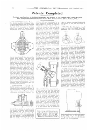
CHA N GE-SPEED GEAR. —Roots. — No. 25,468, dated 2nd November, 1910. —In this specification there is described a change-speed transmission and reversing gear which is mounted on the back axle of the vehicle, or upon a similar driven shaft in any other circumstances.
On the propeller shaft there is secured a double bevel pinion. The quter and smaller of these meshes with two large bevel wheels mounted in suitable bearings carried on the casing of the axle. One of these therefore is rotated in one direction and the other in the reverse direction. The inner and larger bevel pinion drives a second large bevel wheel running in bearings situated in one of the first large bevel wheels; these three large bevel wheels are all concentric with the driven shaft. Two clutches are provided by which, on the left-hand side, either ot the two large bevel wheels may be clutched to the differential, or, on the right-hand aide of the large bevel. wheel may be clutched to the differential to give a reverse drive; thus two speeds and a reverse may be obtained. Various modified forms of construction are also described and illustrated.
CARBURETTER.—Lamplaugh.—No. 25,745, dated 5th November, 1910.—The carburetter described and illustrated in this specification is designed to be of very compact form of float-feed and to offer special facilities for cleaning. An annular float chamber is supplied with fuel through an ordinary needle valve on the left-hand side. A central vertical passage, composed of various tubes fitting inside one another, is formed through the float chamber. The fuel passes from the float chamber through a wire gauze into an annular recess formed in the outermost tube and from thence by inclined passages at the bottom of the recess inwards to an annular space formed between two of the tubes. The jet nozzles are formed by slots cut in the lower edge of a ring which fits the top of this inner annular space, and these are covered or uncovered by a slotted tube resting upon them. The main air inlet is at the top of this vertical tube, and the air travelling downwards passes across the jets into a horizontal mixing chamber, where additional air is introduced through spiral guides, and the mixture passes by a lateral passage to the cylinders. The sleeve controlling the jets is preferably interconnected with the valve controlling the extra-air inlet, so that a suitable mixture is obtainable for all speeds.
I NJ EC TOR.—G resh am.-No. 1,998, dated 26th June, 1911.—This invention relates to injectors and has for its object to provide means for allowing the escape of hot water which remains in the injector when the steam supply is cut off. In the construction illustrated the injector is coupled on to this device immediately above it. The main water intake is the large tube on the right,
and a non-reture valve is provided in a suitable seating, so that the water can be drawn up, but will not pass back into the hot well after being heated, and thus impair the action when the injector is restarted. A by-pass return valve is provided, preferably with a ball-cock which is dosed, when the injector is at work, by suction, but which, when the steam is cut off, drops and opens a path for the hot water to he discharged. The automatic valve in the main water conduit is provided with a screwed-spindle which is normally left in its mid-position and so allows the
valve to operate; this may be screwed up or down to hold the valve open or closed.
CUT-OUT.—The Birmingham Small Arms Co., Ltd.—No. 28,623, dated 9th December, 1910.—This invention relates to cut-outs for exhausts for silencers and has for its object to provide a simple construction of operating mechanism in which the same movement of the operating pedal alternately opens and closes the exhaust outlets. A spring-pressed plunger has pivotally attached to it a link having a pin lying in a slot in the plate which covers the exhaust outlet. 'This slot is so shaped that, when the plate is in the "open " position, the pin engages with a cam surface when depressed and so operates to close the exhaust holes. When the pin returns to its inoperative position, it is then opposite the second cam surface, upon which it operates to open the exhaust nutlet.
VALVE-GEAR CASING.—Renault.No. 12,578 of 1911, dated under International Convention, 28th May, 1910.— This invention relates to internal-combustion engines and refers particularly to valve-gear casing therefor which communicates with the crank casing in such a manner that, during the working of the engine an atmosphere permeated with oily vapour will be maintained in the valve casing. The valve stems and their springs are arranged in a chamber comprised between the outer wall of the cylinders and a partition fixed thereon. This chamber communicates on the one hand through an orifice with the interior of the casing and on the other hand, through another orifice covered with wire gauze, with the atmosphere.