


Abridgments of Interesting Patent Specifications.
Page 24
If you've noticed an error in this article please click here to report it so we can fix it.
Vaporiser ; Lubricator ; Carburetter; Change Gear.
No. 14,853, dated July :9th, 19(25.— Vaporiser.—Paxman.—The exhaust is admitted through a chamber (A) by a passage (2), and finds its exit at (a1). Within the
• chamber (A) is a sleeve (D) surrounded • by a casing (13), and a small annular space is left between the sleeve and casing. The fuel, mixed with a little air, enters at E and passes through a passage (C) into the annular space between the members (B
and D). It leaves this space by a passage (CI), within which are radiator baffles (c). The conduit from CI extends into a casing (J), within which a burner may be mounted for the purpose of finally beating the outgoing charge. The incoming air is heated by passing it between an apron (G) and the exterior of the hot chamber (A).
ag,652, dated December 31st, 1904—Lubricator.—Johnston and the Mo-Car Syndicate.—Within a casing (A) a rotatable liner (D) is mounted, driven by gear
ing (G). One end of the liner is open, and into this projects a pipe (J), by which the lubricant is supplied. The open end of the liner has an inwardly turned flange (II), and as more lubricant is supplied than used, that in the liner is always tnaintained at the level of the flange, the
'surplus passing away by the pipe (K). The liner is perforated obliquely, as shown at L, and these perforations are in line with the lubricating tulles (B), which enter the casing (A) above the level of the lubricant. Each perforation in the liner is filled with lubricant as it traverses the :lower portion of the lubricator, and discharges its contents into the tube with 'which it is in line. The number of orifices (L) for each tube is varied according to the amount of lubricant required for each part of the mechanism.
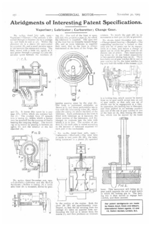
No. 12,780, dated June 20th, Carburetter.—MacLeod.—The inlet tube is made in two parts (B) (131), the latter being connected to a piston (E) operated by the suction of the engine. Both the parts (B) (B1) are approximately coneshaped, so that the air entering from the passage (C) takes an annular form surrounding the fuel as it issues from, the nozzle (r), and thus produces an intimate mixture. To steady the part (111) in its movements a dash pot (h) (hi) is provided.
No. 26,25o, dated December 2nd, 1904. —Change-speed Gearing.—Marshall.—The controlling mechanism is locked so that only one set of gears can be in engagement at a time, and before a change of speed can be made the gears must be all thrown out of action. Two hand-operating levers (a) (b) are linked respectively to two parallel sliding bars (e) (f). These bars have out of gear notches (h) (i) and in gear notches (q) (r), the latter notches being only half the width of the former ; (j jI) is a locking key, which cannot he moved from an in gear notch except into an out of gear notch, so that only one set of wheels can be in engagement at a time. In operation, the locking key is liberated, and then pushed to an extreme position into one of the out of gear notches in one of the bars (e) (1), thus freeing the other bar, which can be moved by its hand lever. This movement will bring an in gear notch opposite the out of gear notch in which the locking pin is. The locking key is then moved to engage both notches, and there secured.