


A Clever Stabilizer Design
Page 43
If you've noticed an error in this article please click here to report it so we can fix it.
Details of a Torsion Tube Device Fitted to Prevent Roll in the A.E.C. Regent Mark Ill Chassis
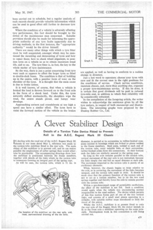
I N dealing with the road test of the A.E.C. Regent Mark III chassis in our issue dated May 2, reference was made to the torsion-tube stabilizer fitted to the rear'axle. The main object of this stabilizer is to prevent roll, and its use makes possible the employment of softer springs than would other-. wise be practicable. The accompanying drawings show how the stabilizer is positioned between the frame members, together with details of the links which tie the torsion tube to extensions forming an integral part of the spring caps.
As will be seen, the torsion tube, which is 31 ins, in diameter, is carried at its extremities in rubber-bushed trunnions located in housings which are bolted to plates welded to the frame members. Steel arms, welded to each end of the torsion tube, carry suitable linksat their extremities; rubber-bushed joints form the connections. At their bottom ends the links. are similarly secured to the spring caps.
So long as the axle remains parallel to the torsion tube, vertical movement of the rear axle is not restrained, because the links simply rise and fall an equal distance at each side. The movement imparted to the torsion Labe is purely of an oscillatory character.
,When, however, the chassis begins to twist relative to the axle, as in cornering, the movement of the links becomes unequal, and the torsion tube tends to twist. It should be made clear that the primary function of the torsion tube is not to act as a torsion member, but to tie the two road springs together and thereby force the axle to remain parallel with the torsion tube.
Within a pre-determined range of permissible oscillations, the effect of the stabilizer is not felt. Such a condition would apply when the vehicle was encountering normal irregularities in the road surface. The device which permits of this free motion forms part of one of the two vertical links, and consists of a small steel piston operating in a cylinder, with suitable rubber stops introduced to limit the travel of the piston.
Whilst the A.E.C. stabilizer is at present fitted to only the rear axle of the Regent Mark III, the maker intends to fit to the front axle a stabilizer operating on the same principle. Development work in this connection is still being carried out.