


Steerable Live-axle Design
Page 42
If you've noticed an error in this article please click here to report it so we can fix it.
A Résumé of Patent Specifications That Have Recently Been Published
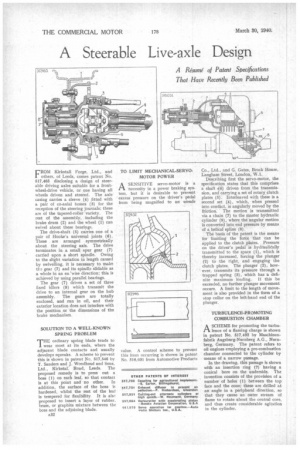
FROM Kirkstall Forge, Ltd., and others, of Leeds, comes patent No. 517,465 disclosing a design of steerable driving axles suitable for a frontwheel-drive vehicle, or one having all wheels driven and steered. The axle casing carries a sleeve (4) fitted with a pair of co-axial bosses (3) for the reception of the steering journals; these are of the tapered-roller variety. The rest of the assembly, including the brake drum (2) and the wheel (1) can swivel about these bearings.
The drive-shaft (5) carries one of a pair of Hooke's universal joints (6). These are arranged symmetrically about the steering axis. The drive terminates in a small spur gear (7) carried upon a short spindle. Owing to the slight variation in length caused by swivelling, it is necessary to make th.1 gear (7) and its spindle slidable as a whole in an en 'wise direction; this is achieved by using parallel bearings.
The gear (7) drives a set of three fixed idlers (8) which transmit the drive to an internal gear on the hub assembly. The gears are totally enclosed, and run in oil, and their exterior location does not interfere with the position or the dimensions of the brake mechanism.
SOLUTION TO A WELL-KNOWN SP RING PROBLEM THE ordinary spring blade tends to
wear most at its ends, where the adjacent blade contacts and usually develops squeaks. A scheme to prevent this is shown in patent No. 517,546 by T. Sanders and J. Woodhead and Sous, Ltd., Kirkstall Road, Leeds. The proposed remedy is to press out a boss (1) on each leaf, so that contact is at this point and no other. In addition, the surface of the boss is hardened, whilst the rest of the leaf is tempered for flexibility. It is aisr proposed to insert a layer of rubber, brass, or graphite mixture between the boss and the adjoining blade.
A32
ASENSITIVE servo-motor is a necessity in a power braking system, but it is desirable to prevent excess pressure on the driver's pedal from being magnified to an unsafe
value. A control scheme to prevent this from occurring is shown in patent No. 516,031 from Automotive Products Co., Ltd., and G. Gates, Brock House, Langham Street, London, W.I.
Describing first the servo-motor, the specification states that this comprises a shaft .(6) driven from the transmission, and carrying a set of rotary clutch plates (5). Interleaved with these is a second set (4), which, when pressed into contact, is angularly moved by the friction. The motion is transmitted via a chain (7) to the master hydraulic cylinder (9), where the angular motion is converted into end pressure by means of a helical spline (8).
The basis of the patent is the means for limiting the force that can be applied to the clutch plates. Pressure on the driver's pedal is hydraulieally transmitted to the space (1), which is thereby increased, forcing the plunger (2) to the right, and engaging the clutch plates. The plunger (2), however, transmits its pressure through a trapped spring (3), which has a definite maximum loading. If this he exceeded, no further plunger movement occurs. A limit to the length of movement is also provided in the form of a stop collar on the left-hand end of the plunger.
TURBULENCE-PROMOTING COMBUSTION CHAMBER
ASCHEME for promoting the turbulence of a flaming charge is shown in patent No. 517,432 by Maschinenfabrik Augsburg-Nurnberg A.G., Nurnberg, Germany. The patent refers to oil engines employing a pre-combustion chamber connected to the cylinder by means of a narrow passage.
In the drawing, this passage is shown with an insertion ring (2) having a conical bore on the underside. The invention consists of the provision of a number of holes (1) between the top face and the cone; these are drilled at an angle in a peripheral direction, so that they cause an outer stream of flame to rotate about the central core, and thus create considerable agitation in the cylinder.