 1
1 2
2 3
3 4
4 5
5 6
6 7
7 8
8 9
9 10
10 11
11 12
12 13
13 14
14 15
15 16
16 17
17 18
18 19
19 20
20 21
21 22
22 23
23 24
24 25
25 26
26 27
27 28
28 29
29 30
30 31
31 32
32 33
33 34
34 35
35 36
36 37
37 38
38 39
39 40
40 41
41 42
42 43
43 44
44 45
45 46
46 47
47 48
48 49
49 50
50 51
51 52
52 53
53 54
54 55
55 56
56 57
57 58
58 59
59 60
60 61
61 62
62 63
63 64
64 65
65 66
66 67
67 68
68 69
69 70
70 71
71 72
72 73
73 74
74 75
75 76
76 77
77 78
78 79
79 80
80 81
81 82
82 83
83 84
84 85
85 86
86 87
87 88
88 89
89 90
90 91
91 92
92 93
93 94
94 95
95 96
96 97
97 98
98 99
99 100
100 101
101 102
102 103
103 104
104 105
105 106
106 107
107 108
108 109
109 110
110 111
111 112
112 113
113 114
114 115
115 116
116 117
117 118
118 119
119 120
120 121
121 122
122 123
123 124
124 125
125 126
126 127
127 128
128 129
129 130
130 131
131 132
132 133
133 134
134 135
135 136
136 137
137 138
138 139
139 140
140 141
141 142
142 143
143 144
144 145
145 146
146 147
147 148
148 149
149 150
150 151
151 152
152 153
153 154
154 155
155 156
156 157
157 158
158 159
159 160
160 161
161 162
162 163
163 164
164 Power Steering Control Valve
Page 122
If you've noticed an error in this article please click here to report it so we can fix it.
IMPROVEMENTS in valves controlling I the pressure fluid in a powered steering system form the subject of patent No. 865,759. (R. Bishop, R. Johnson and G. Whitlock, 28 Marlborough Road, Luton.) The valve is shown in section in the drawing. A sliding member (1) has a narrow close-fitting land (2) in the middle. This co-operates with an inlet port (3) and two outlets (4 and 5) which lead to each end of the servo-cylinder. An exhaust port (6) leads back to the pump.
In the central position shown, the incoming fluid divides into two streams HYDRAULIC ACTUATOR IMPROVEMENTS DATENT No. 865,223 refers to 1 hydraulic actuators of the type in which a vane moves through a sectorShaped chamber. The efficiency of such devices depends entirely on the accuracy of the fit of the vane, and to improve this is the object of the scheme disclosed. (Girling, Ltd., Kings Road, Tyseley, Birmingham, 11.) In the drawing, a section of a typical chamber containing the moving vane (1)
's shown. Instead of machining the inner curved surface (2) accurately, which is an expensive operation, it is proposed to leave it as cast. To form a seal, a curved plate (3) is inserted and held in position by two end rods. The curved plate is said to be easily manufactured to the required degree of accuracy.
The closeness of fit is controlled by an adjustment consisting of a screw (4) pressing on the outside of the liner.
CONVEYOR FITTED BODY A BODY designed for the rapid load
ing and discharge of heavy solid materials such as coke is shown in patent No. 865,097. The body may also be of use on a building site to shift or elevate material, (Concrete Carrying Co., Ltd., Pilling Street, Rochdale Road, Manchester, 4.) The body is constructed in the form of a hopper and at the bottom it is provided 1340 which pass through end chambers (7) and out of the exhaust port.
If the spool is moved to the right, it stops the right-hand flow and directs all the fluid pressure to the left, the exhaust port being cut off by a face-valve (8).
On the return stroke the face-valve opens to give a very rapid change of pressure.
Movement of the spool to the left directs fluid to the right-hand outlet, and the spring (9) ensures that the spool is normally retained in a central position.
with a belt conveyor (I) for discharging the load at the rear.
In addition to the internal conveyor, an external one is carried on the outrigger (2). Normally housed under the body, it can be drawn out into the operative position illustrated. It is supported by a jib which can swing sideways on pivots (3). The jib can also be raised or lowered by an hydraulic cylinder (4). The power for driving the conveyor is also transmitted hydraulically.
A consecutive patent numbered 865,098 deals with other aspects of the scheme.
PORTABLE CEMENT SILO
Pl.A STORAGE vessel for cement that can also be used for transporting it forms the subject of patent No, 864,868. Though described particularly for cement, the patent covers the use of the scheme for any powdered material. (Road Machines (Drayton), Ltd., Horton Parade, West Drayton, Middlesex.)
The drawing shows the container (1) in the transport position in which it functions as a trailer. The cylindrical body is arranged to pivot about the point (2).
Opon arrival at the site. the container is raised to a vertical position and the contents discharged by gravity from an opening (3). Compressed air may be blown into the interior to expedite the outflow. DIESEL ENGINE COMBUSTION SYSTEM
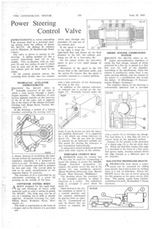
PATENT No. 865,536 refers to oilengine pre-combustion chambers in which the fuel charge, instead of being atomized by a fine jet, is spread in a thin film over the wall of the chamber. According to the specification, while this scheme is satisfactory under load, it can make starting difficult, and the subject of the patent is a modification that avoids this defect. (J. Effenberger, 55 Mainzerstrasse, Bingen, Germany.)
The chamber shown in the drawing is substantially spherical and is provided with a nozzle (1) to introduce the charge. The fuel flows in a thin film (2) over a narrow band of the spherical surface.
Essence of the scheme is the provision of a sharp edge (3) to the air entry duct (4). When the fuel film reaches this edge it is detached in the form of a fine spray that ignites easily. Another scheme shows the edge located at a different part of the chamber.
BALANCING PROPELLER SHAFTS
APROPELLER shaft which is unbalanced can be corrected by adding mass locally, but if this is done by welding there is a risk of distortion. Patent No. 863,478 covers the use of metal spraying for this purpose as the spray carries little heat. The patent comes from Gelenkwellenbau G.m.b.H., Westendhof 7, Essen, Germany.