


Two-leading-shoe Brake with Two Expanders
Page 36
If you've noticed an error in this article please click here to report it so we can fix it.
A Resumi• of 'Patent 541617
Specifications That Have Recently Been Published. Copies may be Obtained from the Patent Office,
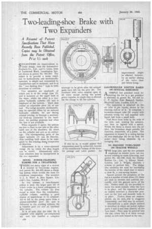
Pr.ce 11each SUGGESTIONS for improvement in brake design, from the Automotive Products Co., Ltd., and G. Gates, both of Tachbrook Road, Leamington Spa, are shown in patent No. 541,617. The object is to provide a brake which can be hydraulically and mechanically operated, is simple and economical to manufacture and to maintain, and is of the " two leading shoe " type in both directions of rotation.
Two spreaders are employed, of which one is of the wedge type (1) and is mounted at the upper ends of the shoes, whilst the other is a twopiston 'hydraulic cylinder (2) and is employed at the bottom. Each shoe carries an adjustable piece (4) at one end. The wedge spreader, incidentally, may be operated either by an external hydraulic cylinder, for use during normal driving, or through a mechanical hook-up connected to the handlever, for parking purposes and when the foot is not available.
When expander 2 opens, the pistons are free to float to one side or the other until one of the shoulders (3) abuts on the cylinder and acts as an anchorage. The corresponding parts of the . upper spreader (1) can do likewise. thus enabling both shoes to be energized by the. rotating druni irrespective of direction.
Adjustment is by a screw-operated wedge (5) by which the shoe length
can be varied. Alternatively clicktype adjusters may be incorporated in the two expanders.
• NOVEL POWER-CHARGING SCHEME FOR A TWO-STROKE ' THERE are many signs of a revival 1 of interest in two-stroke engines, and patent No. 541,372 shows a charging system which avoids the need for crankcase compression. The inventor is J. A. Shaw, 9, New Square, Lincoln's Inn, London, -W.C.2.
In this scheme, a two-diameter piston is used, the larger part (4) of which works in a lower enlargement of the cylinder. The volume (2) thus swept is more than the combustioncylinder volume, enabling a good degree of supercharge to be attained. Air is fed to the pump space from a piston-controlled port (3) and is delivered to the working cylinder via a transfer port (1) and an overhead inlet valve.
It is of note that the inlet (3) is supplied with slightly; pre-compressed. air, and this enables a complete scavenge to be given after the exhaust gases have left via the port (5). The overhead inlet valve remains open at all times except during the actual power impulse, so ample time is allowed for the charge to fill the cylinder.
If this be so, it would appear that compression must be rather low, because of the considerable ‘7olume of the transfer passage and valve pocket. An
GAS-PRODUCER IGNITER BASED ON OFFICIAL RESEARCH ASIMPLE but practical torch for starting the fire in a gas prodUcer. is disclosed in patent No. 541,416 by C. P. Sayles, Fuel Research Station, Blackwall Lane, London, S.E.I0. • The apparatus is attached to the air inlet of he tuyere, shown in the drawing end-on at 2. It comprises a horseshoe-shaped tube (9) wound with asbestos string (1) and supplied with liquid fuel from a small tank.
Fuel flows from holes in the ends of the tube, and, soaking the asbestos, can then be lighted with a match. Whilst the flame is drawn into the air inlet, the horseshoe shape permits the insertion, meanwhile, of a poker. The apparatus is housed in a casing having its own stack-pipe (4) for air feed, the poker door being closeable by a swinging disc.
TO PREVENT TYRE-CREEP ON TRACTOR WHEELS
THE large size, and the low pressure employed on tractor tyres, are two factors tending to cause tyre-creep, and patent No. 541,740, from the Dunlop Rubber Co., Ltd., 1„ Albany Street, London, and J. Wright, discloses a scheme to prevent this, The design also -abolishes the need for machining the interior of the wheel rims to ensure a close fit, a cost-saving feature.
Spaced around the periphery of the rim is a number of loose shoes (1); these are sunk in recesses and conform outwardly with the general curve of the rim. Pusher studs (2) are provided to move the shoes radially when the tyre is in place, and the expansive action so caused exercises a chuck-like pressure on the tyre and securely locks it
in place. Twelve shoes are contemplated, six on each, side in staggered relationship, and they may be serrated.
Alternatively a more simple method is described in which set screws replace parts 1.and 2 and bear directly on the tyre bead. They may be screwed into the rim, where this is of thick enough metal, or into nuts brazed to the rim.