


Pa tents Completed.
Page 20
If you've noticed an error in this article please click here to report it so we can fix it.
IIAPORISER.—Brown and Barlow.— —No. 26,750, dated 24th November, 1906, —The oil supplied to the float chamber
(a) passes through a coil (6) arranged within the exhaust pipe (d). The exhaust pipe (d) is divided by a partition (e) and, at the end where the exhaust gases enter, a. flap valVe (f), by means of which the direction of the gases can be regulated, is arranged. At the other end of the exhaust pipe (d), inclined baffle plates (g) which direct the exhaust gases into the conduit (i) through an orifice (b), are placed. The exhaust gases pass through the conduit (1) into a conical hood (Iz) surrounding the jet (1). At the moment when the oil is leaving the jet (b), in response to the suction of the engine, a quantity of thc hot exhaust gases is drawn through the hood (k1 and impinges on the oil leaving the jet and so vaporises the same. The air for combustion is drawn in through the pipes (1).
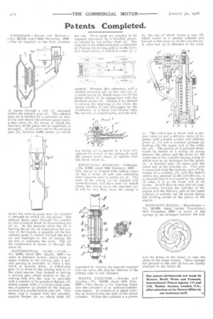
DIFFERENTIAL GEAR,— Frills. — Nn. 6,087, dated 13th March, 1907.—In order to transmit motion direct from a steam turbine to the driving axle, a spe• cial gearing is provided to effect a forward, or reverse, drive. A differential gear (f) is fitted to the driving axle (e) in the usual manner, but, instead of having a driving gear wheel secured to the revolving ease (f1), the case is provided with a number of longitudinal flanges (f2) which engage with a corresponding number of grooves (g) formed on the internal surface of a second hollow case (g1). This latter case is formed with two parallel, angular flanges (h), on which teeth (41) are cut. These teeth are adapted to be engaged separately by a bevelled pinion (i) carried by the cardan shaft (4 The case (f1) of the differential gear is extended at /3 along the driving axle (e) in the form of a loose sleeve, to which a collar (f) is secured. Between this extension, and a similar extension tg2) on the case (g1), is a spiral spring (4) Which keeps one of the bevel wheels (h) in engagement with the bevelled pinion (1). Should it be desired to reverse the direction of the drive, the spring catches (1) are disengaged by the contraction of a band (not shown) after the manner of a band brake, and the slid iag casing (0) is Tnoved by a lever (”211 against the action of the spring (4) until the second bevel wheel (4) meshes with the bevel wheel (1).
EXPANDING REAMERS.—Oubridge. —No. 3 863, dated 16th February, 1907.— The casing (a) formed with cutting edges ()) has a aeries of saw cuts extending from opposite ends to points (a?, ti). The ends of the casing (z) are tapered and screw-threaded and have nuts (J) which clamp the casing on to the mandrel (g), It will be seen that, when the casing is
expanded by forcing the tapered mandrel into the same, the angular relation of the cutting edge is not changed.
WATER INJECTOR.— Scholes and Another.—No. 16,949, dated 24th July, 1907.—This device is for injecting water into the cylinders of an internal-combustion engine. It consists of a small cylinder (a) screwed into the wall of the motor cylinder. Within this cylinder is a piston (4), the rod of which forms a ram (41) which works in a smaller cylinder (at) formed in the cover (c) of the cylinder (a). A valve box (d) is attached to the cover ((). This valve box is fitted with a suction valve (e) and a delivery valve (I) together with suitable suction and delivery ports (el, fl) and a common passage (g) leading into the upper end of the cylinder (al). The piston .(4) is pressed downwards by means of a spring (J) acting between the piston and the cover (c), the lower end of the cylinder having a ring (1) which acts as an abutment for the piston . A delivery port (f2) opens iato the lower end of the cylinder (a). This port is connected with the delivery port (f) by means of a conduit (P), and the latter's orifice (w), situated in the cylinder (a), is so located that it is covered by the piston (1) when it is at the lower end of its stroke. It will thus be seen that all communication between the cylinder of the engine and the delivery port of the water injector, is entirely cut off except during the working stroke of the piston of the engine.
RESILIENT WHEEL.—Mannberger.— No. 28,889, dated (under Convention) 18th December, 1905.—A series of flat springs (1) are arranged between the hub
and the feline of the wheel, to take the place of the usual spokes. These springs are pivoted to the hub (2) but are rigidly attached to the felloe (3).