Dual Reservoirs for Compressed-air Braking System
Page 44

If you've noticed an error in this article please click here to report it so we can fix it.
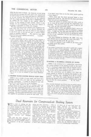
yyJITH a view to cutting out the VV delay which is caused as the result of a driver having to wait until the air pressure builds up in the reservoir of a compressed-air braking system. the Westinghouse Brake and Signal Co„ 'Ltd., 82, York Way, King's Cross, London, N.1, has introduced a combined reservoir and charging valve.
This unit has been designed to ensure that an adequate supply of compressed airwill he available within a few moments of the air compressor
a34 being got into operation. This is achieved by arranging for a two-part reservoir, one section being of such capacity that it becomes charged in a few seconds, and thus makes available sufficient air to provide for effective application of the brakes.
Interposed between the small and large reservoir is a charging valve, which allows air to pass into the main reservoir when the small one is charged, full pressure, however, being maintained in the latter. There is also a check valve, suitably arranged so as to allow air to pass back from the large reservoir to maintain the pressure in the small one when the former is fully charged.
In addition to the valves mentioned, the valve mechanism includes an unloader for the compressor, when the latter is not electrically driven, the usual check valve between the compressor and first reservoir, and a safety valve.
The unit is mounted so that all the valves can be removed without the need for breaking pipe connections.


