


A Dual-function Oil Filter A Résumé of Patent Specifications That
Page 34
If you've noticed an error in this article please click here to report it so we can fix it.
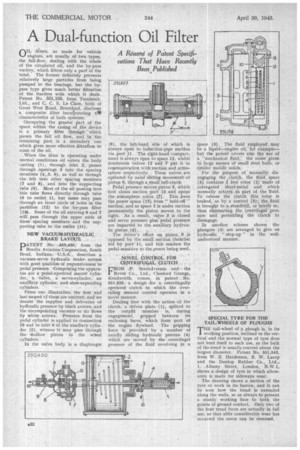
Have Recently Been Published OIL,filters, as made for vehicle engines, are usually of two types, the full-flow, dealing with the whole of the circ,ulated oil, and the by-pass variety, which filters only a part of the total. The 'former definitely prevents relatively large particles from being pumped to the bearings, but the bypass type gives much better filtration of the fraction with which it deals. Patent No. 551,158, from Tecalemit, Ltd., and C. C. S. Le Clare, both of Great West Road, Brentford, discloses a composite filter incorporating VI* characteristics of both systems.
Occupying the greater' part of the space within the casing of the device is a primary filter throu,gh which passes the full oil flow, and in the remaining part is a secondary one which gives more effective filtra5on to some of the oil.
When the filter is operating under normal conditions oil enters the body casting (1), through inlet 2, passes through openings 8 into the spacing members (4, .5, 6), as well as through the felt into other spacing members (7 and 8), and into the supporting tube (9). Most of the oil passing into 'this tube flows directly through tithe 10 to outlet 11, but some may pass through an inner circle of holes in the partition (12) to the by-pass filter (11). Some of the oil entering 6 and 7 will pass through the upper ends of these spacing members and the supporting tube to the outlet (14).
NEW VACUUM-HYDRAULIC BRAKE LAYOUT.
DATENT No.-7..550,:450,from the Bendix Aviation:Corporation, South Bend, Indiana, us A describesa vacuum-servo hydraulic brake system With good qualities of responsiveness ter pedal pressure. 'CoMprising the apparatus are a pedal-operated" master cylinder,: "valve, a servo-cylinder, an auxiliary cylinder, and.shae-expanding cylinders. . •
From our illustration' the first and last named of these ate omitted, dnci we denote the supplies and deliveries of hydraulic pressure by black arrows, and the corresponding vacuum Or air flows by white arrows: Pressure • from the pedal cylinder is applied to connection 10 and to inlet 6 of the auxiliary cylinder (5), whence :it may pass through the -*hollow piston to the wheel cylinders.
In the valve body is a diaphragm
(8), the left-hand side of ,which is always open to induction-pipe suction via port 11. The right-hand compartment is always open to space 13, whilst mushroom :valves 12' and 7 piit it in communication with suction and atmosphere respectively. These valves are operated by axial sliding movement of piston 9, through a small bell-crank Pedal pressure moves piston 9, which 'first closes suction port 12 and opens. the atmosphere valve (7), This frees tne power space (IS) from "hold-off " suction; and as space 2 is under suction permanently the piston moves to the right. As a result, valve 3 is closed and servo pressure plus pedal pressure are imparted to the auxiliary hydrau lic piston, (4)„. . .
The driver's effort on piston, 9 is opposed by the small suction CharabUr fed 'by port 11, -and this renders the pedal sensitive to the power being used.
. . • , NOVEL CONTROL FOR CENTRIFUGAL CLUTCH CROM _P, Scott-Iversen and the Rover Co., Ltd., Chesford Grange, Kenilworth, comes, in patent No, 551,623, a design for a centrifugally operated clutch in which the overriding manual control operates in a novel manner.
Dealing first with the action of the clutch, a driven plate (1), splined to the outpfit Member is, during engagement, gripped between its enclosing faces, which form part of the engine flywheel. •The gripping force 'is provided by a number of axially sliding hydraulic pistons (4) which are moved by the centrifugal pressure of the fluid revolving in a
space (5). The fluid employed may be a liquid—engine oil, for example— but the patent covers also the use of a "mechanical fluid,' the name given to large masses of small steel balls, or :similar mobile For the purpose of manually disengaging the clutch, the fluid space (5) contains a free rotor (2) made of corrugated sheet-metal and which ' normally rotates. as part of the -fluid. To release the clutch this rotor is braked, ' as by a control 3);, the fluid is brought to &standstill, or nearly so, thus eliminating the, centrifugal .pressure and permitting the clutch to disengage.
In another scheme shown the plungers (4) are arranged to give an hydraulic " step-up" in the wellunderstood manner.
SPECIAL TYRE FOR THE TAIL-WHEELS OF PLOUGHS 'THE tail-wheel of a plough is.. in its